Passage block and manufacturing method thereof

a technology of passage block and manufacturing method, which is applied in the direction of valve housing, soldering apparatus, manufacturing tools, etc., can solve the problems of reducing the cooling efficiency of the process, baking or other defects, and the hole deeper than a predetermined depth is difficult to form, so as to facilitate the position of the gask

Inactive Publication Date: 2011-11-17
CKD
View PDF1 Cites 0 Cited by
  • Summary
  • Abstract
  • Description
  • Claims
  • Application Information

AI Technical Summary

Benefits of technology

[0031]The diffusion bonding is performed by placing surfaces in contact with each other and heating them under pressure. To provide passages in the bonded first and second block members, therefore, the first and second coupling faces have to be bonded to each other without gaps therebetween to prevent fluid leakage. In this regard, the first and second passage-end contact portions are diffusion-bonded in contact with the other, providing smaller contact areas than the case where the first and second coupling faces are bonded to each other over the entire surfaces. Thus, the processing accuracy can be enhanced to prevent the occurrence of fluid leakage.
[0034]Preferably, the above passage block further comprises: a first coupling protrusion formed to protrude from the first coupling face around the first-coupling-face aperture and include the first passage-end contact portion; and a second coupling protrusion formed to protrude from the second coupling face around the second-coupling-face aperture and include the second passage-end contact portion. This makes it possible to reduce a surface area to be finish-processed (hereinafter, a “finish processing area”), which is required for diffusion bonding, and easily ensure the necessary surface accuracy. As the finish processing area is larger, processing irregularity may occur, leading to bonding failure. However, the reduction in finish processing area needed for bonding can decrease the possibility of bonding failure.
[0039]Since the aperture area on the downstream side is smaller than the aperture area on the upstream side, the crystallized gas even when formed in the shoulder can be eliminated advantageously.
[0040]Preferably, the passage block further comprises a gasket interposed between the first and second block members to couple the first-coupling-face aperture and the second-coupling-face aperture, and wherein the first passage-end contact portion and the second passage-end contact portion are placed in contact with the gasket respectively and diffusion-bonded to each other to form the passage-end contact section.Accordingly, the bonding faces of the gasket and the first and second passage-end contact portions are finish-processed and diffusion-bonded to each other. Consequently, the finish area can be reduced, and the pressure required for pressing can be reduced, contributing to downsizing of a pressure device.
[0042]Accordingly, the area of an upstream-side aperture of the gasket is smaller than the area of the first-coupling-face aperture and the area of the second-coupling-face aperture is smaller than the area of a downstream-side aperture of the gasket. Thus, the areas of the apertures in respective coupling portions are always larger on the upstream side than on the downstream side, which can prevent the occurrence of a fluid stagnation region in the passage.
[0045]Preferably, the above method of manufacturing the passage block, further comprises the steps of: interposing a gasket between the first block member and the second block member to couple the first-coupling-face aperture and the second-coupling-face aperture; and positioning the gasket in place by use of a gasket holding member for holding the gasket so that the gasket is diffusion-bonded to the first and second block members. It is therefore possible to easily position the gasket in place and form the passage without displacement when the first and second block members are bonded to each other.

Problems solved by technology

However, most of the passages formed by this technique are simple in shape because the machining requires a space enough for a cutting tool such as an end mill and a drill to enter, thus inevitably resulting in a combined form of straight shapes.
For a deeper hole, a cooling efficiency during processing is apt to decrease, causing baking or other defects.
A hole deeper than a predetermined depth would be hard to form.
However, a problem occurs that a stagnation region is generated in the passage.
Such a square outer corner of the passage is likely to cause fluid stagnation.
This stagnated fluid would interfere with fluid replacement.
If the fluid crystallizes in the stagnation region, the flow of purge gas used for purging the passage will weaken in the fluid stagnation region and thus cannot easily blow away resultant crystals.
In the case of a corrosive fluid, the purity of fluid increases when crystallizes, which conceivably causes a problem that it erodes the block body 111 and the lid member 112.
In particular, when a gap occurs between the block body 111 and the lid member 112 due to a bonding failure, undesirably, purging would be more difficult.

Method used


Image

  • Passage block and manufacturing method thereof
  • Passage block and manufacturing method thereof
  • Passage block and manufacturing method thereof

Examples


first embodiment

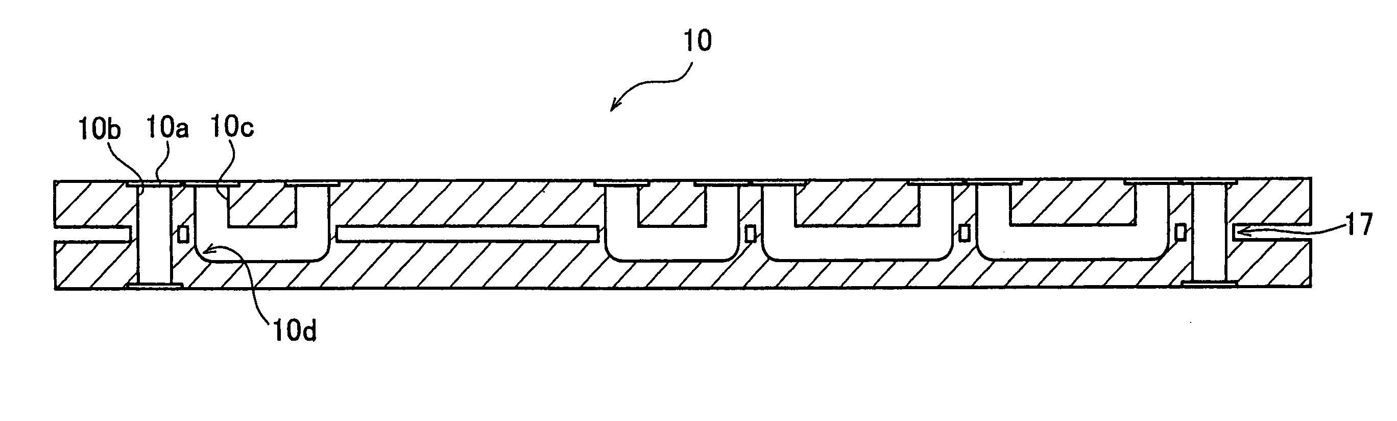
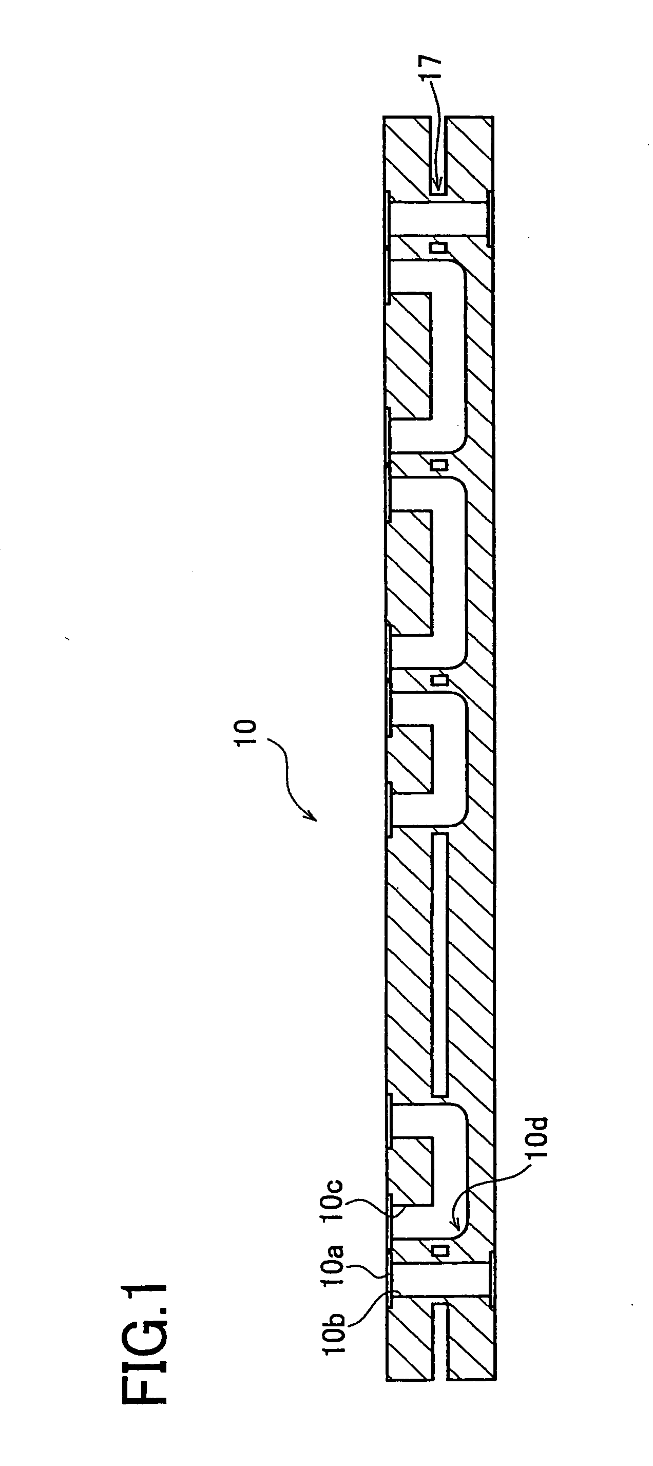
[0076]A configuration of a first embodiment of the present invention is first explained below. FIG. 1 is a sectional view of a passage block of the first embodiment.

[0077]A passage block 10 is usable in a gas integrated unit for use in a semiconductor manufacturing step. On its top surface, fluid control devices not shown for control of gas or the like are mountable and usable in the gas integrated unit.

[0078]The passage block 10 is provided with a plurality of counter bores 10a for gasket, straight passages 10b, and U-shaped passages 10c. Each counter bore 10a holds a gasket not shown through which a fluid control device is to be mounted on the passage block 10. The passage block 10 includes an upper part and a lower part which are diffusion-bonded by a passage-end contact section 17 that joins them as shown in FIG. 1.

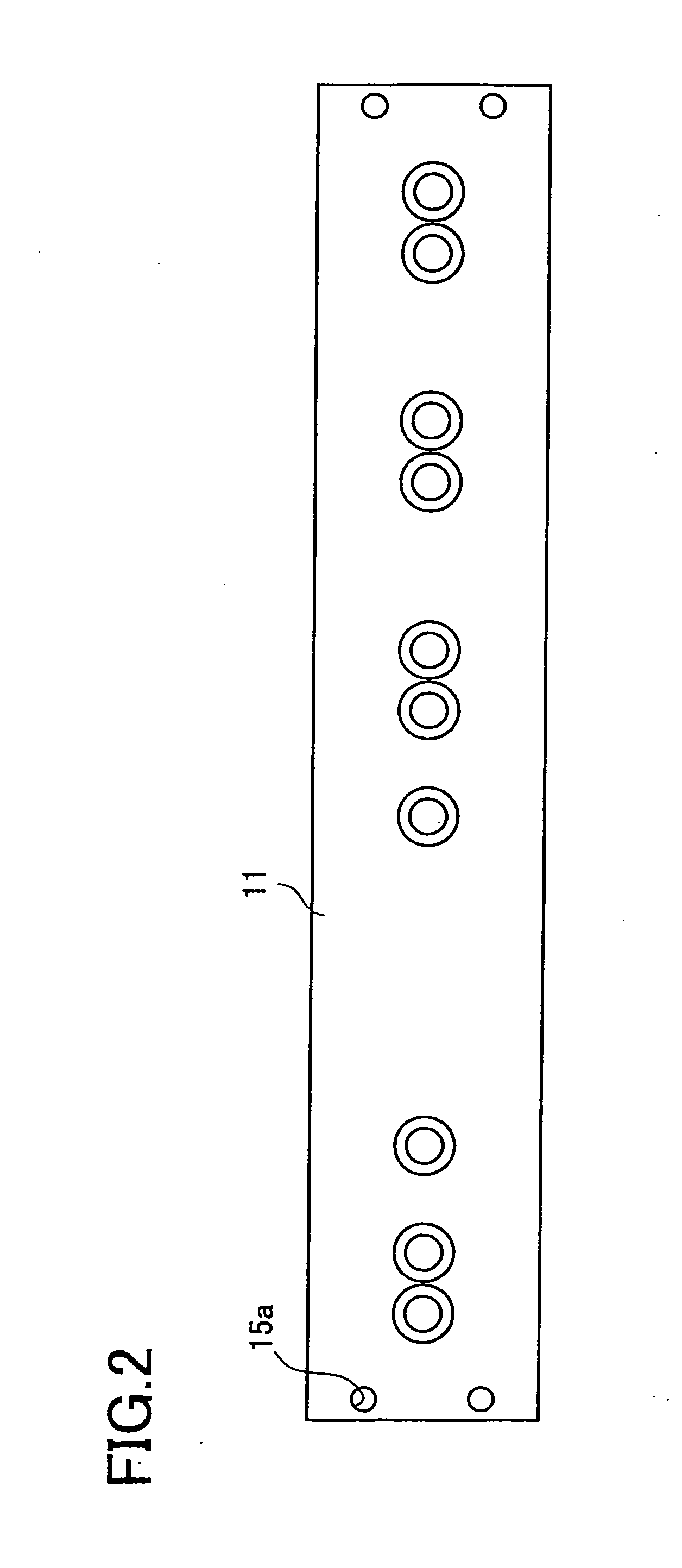
[0079]FIG. 2 is a top view of a first block member 11 constituting the passage block 10 shown in FIG. 1. FIG. 3 is a sectional view of the first block member 11. FIG....

second embodiment

[0117]A second embodiment is similar in structure to the first embodiment excepting a coupling structure of the first and second block members 11 and 12. The following explanation is made with a focus on the differences. Similar components to those in the first embodiment are given the same reference codes.

[0118]FIG. 12 is an exploded perspective partial view of the first and second block members 11 and 12 to be assembled to constitute the passage block 10 in the second embodiment. The lower surface 11b of the first block member 11 is formed with a first coupling protrusion 11e whose end face provides the first passage-end contact portion 17a.

[0119]The upper surface 12a of the second block member 12 is formed with a second coupling protrusion 12e whose end face provides the second passage-end contact portion 17b.

[0120]In the second embodiment, without using the gasket 18 of the first embodiment, the first and second block members 11 and 12 are provided with the first and second co...

third embodiment

[0128]A third embodiment is substantially the same in configuration as the first embodiment excepting the configurations of the first and second coupling-face apertures 11d and 12d. The following explanation is thus made with a focus on the differences.

[0129]FIGS. 13 to 15 are partial sectional views showing a state where displacement occurs when the first-coupling-face aperture 11d and the second-coupling-face aperture 12d are equal in area. Specifically, FIG. 13 shows a state before the first-block lower surface 11b and the second-block upper surface 12a are placed in contact with each other. FIG. 14 shows a state where the lower surface 11b and the upper surface 12a are placed in contact with each other. FIG. 15 shows an enlarged view of part X1 in FIG. 14.

[0130]FIGS. 16 to 18 are views in which the first-coupling-face aperture 11d and the second-coupling-face aperture 12d are bonded in the third embodiment. Specifically, FIG. 16 shows a state before the first-block lower surface...


PUM

PropertyMeasurementUnit
timeaaaaaaaaaa
corrosion-resistantaaaaaaaaaa
diameteraaaaaaaaaa

Abstract

A passage block formed with a passage connectable to a fluid control device comprises a first block member formed with a plurality of first-coupling-face apertures, a second block member formed with a plurality of second-coupling-face apertures in correspondence with the first-bonding-apertures, a first passage-end contact portion formed around each of the first-coupling-face apertures, a second passage-end contact portion formed around each of the second-coupling-face apertures, and a passage-end contact section provided in such a manner that a lower surface of the first block member and an upper surface of the second block member are arranged to face each other so that the first and second passage-end contact portions contact with each other, and the first and second block members are heated under pressure to diffusion-bond the first and second passage-end contact portions to each other.

Description

[0001]This is a Division of application Ser. No. 12 / 003,918 filed Jan. 3, 2008, which claims the benefit of Japanese Patent Application No. 2007-045575 filed Feb. 26, 2007. The disclosures of the prior applications are hereby incorporated by reference herein in their entirety.BACKGROUND OF THE INVENTION[0002]1. Field of the Invention[0003]The present invention relates to a passage block having a complicated passage, which is used in a process gas supply unit, and a manufacturing method of the passage block.[0004]2. Description of Related Art[0005]A process gas supply unit to be used in a semiconductor manufacturing process includes a passage block made of a high-corrosion-resistant stainless block formed with a passage.[0006]This passage is conventionally formed in the passage block by machining. However, most of the passages formed by this technique are simple in shape because the machining requires a space enough for a cutting tool such as an end mill and a drill to enter, thus in...

Claims


Application Information

Patent Timeline
Patent Type & Authority Applications(United States)
IPC IPC(8): B21K1/20
CPCF15B13/0814F15B13/0871Y10T29/49405F16L39/00F16K27/003Y10T137/87885H01L21/02
Inventor MAMYO, MITSURUITOH, KAZUTOSHI
Owner CKD
Why Eureka
Try Eureka