
Image forming apparatus and cleaning method

a technology of image forming apparatus and cleaning method, which is applied in the direction of electrographic process apparatus, instruments, optics, etc., can solve the problems of increasing the torque of the motor which drives the image holder, the surface of the image holder is difficult to clean, and the edge part of the cleaning blade wears

Inactive Publication Date: 2011-11-03
KONICA MINOLTA BUSINESS TECH INC
View PDF8 Cites 19 Cited by
  • Summary
  • Abstract
  • Description
  • Claims
  • Application Information

AI Technical Summary

Benefits of technology

[0012]In view of the circumstances, a main object of the present invention is to provide a technology by which the amount of a lubricant adhering to the surface of an image holder is determined, and poor cleaning of the image holder which occurs depending on the amount of the lubricant adhering to the surface thereof is prevented from occurring.

Problems solved by technology

Consequently, it becomes difficult to clean the surface of the image holder.
Accordingly, the edge part of the cleaning blade is further pulled into the moving direction of the image holder, and hence, wear of the edge part of the cleaning blade progresses.
However, the torque of a motor which drives an image holder increases both the times when the shortage of a lubricant on the surface of the image holder occurs and when the excessiveness of the lubricant thereon occurs.
Therefore, for example, it could happen that although the adhering lubricant amount to the surface of an image holder is excessive, a lubricant is applied more thereto as the torque of a motor of the image holder is large.
In such a case, it raises a problem that the adhering lubricant amount becomes more excessive, and accordingly, adhesive wear of a cleaning blade progresses, and hence, the cleaning blade is even broken.
Thus, it is difficult to determine whether the adhering lubricant amount is short or excessive based on only the magnitude of the torque of a motor which drives an image holder.
Consequently, supply / removal of a lubricant to / from the surface of the image holder in accordance with the adhering lubricant amount thereto cannot be appropriately carried out.
That is, it is difficult to prevent poor cleaning of an image holder caused by the turn-up of a cleaning blade when the adhering lubricant amount is short, and to prevent poor cleaning thereof caused by the adhesive wear, which is resulted from decrease of the cleaning blade's capability of removing a lubricant, of a cleaning blade when the adhering lubricant amount is excessive.

Method used


Image

  • Image forming apparatus and cleaning method
  • Image forming apparatus and cleaning method
  • Image forming apparatus and cleaning method

Examples


Embodiment Construction

[0023]Hereinafter, an embodiment of the present invention is described in detail referring to the drawings.

[0024]First, the structure of an image forming apparatus according to an embodiment of the present invention is described.

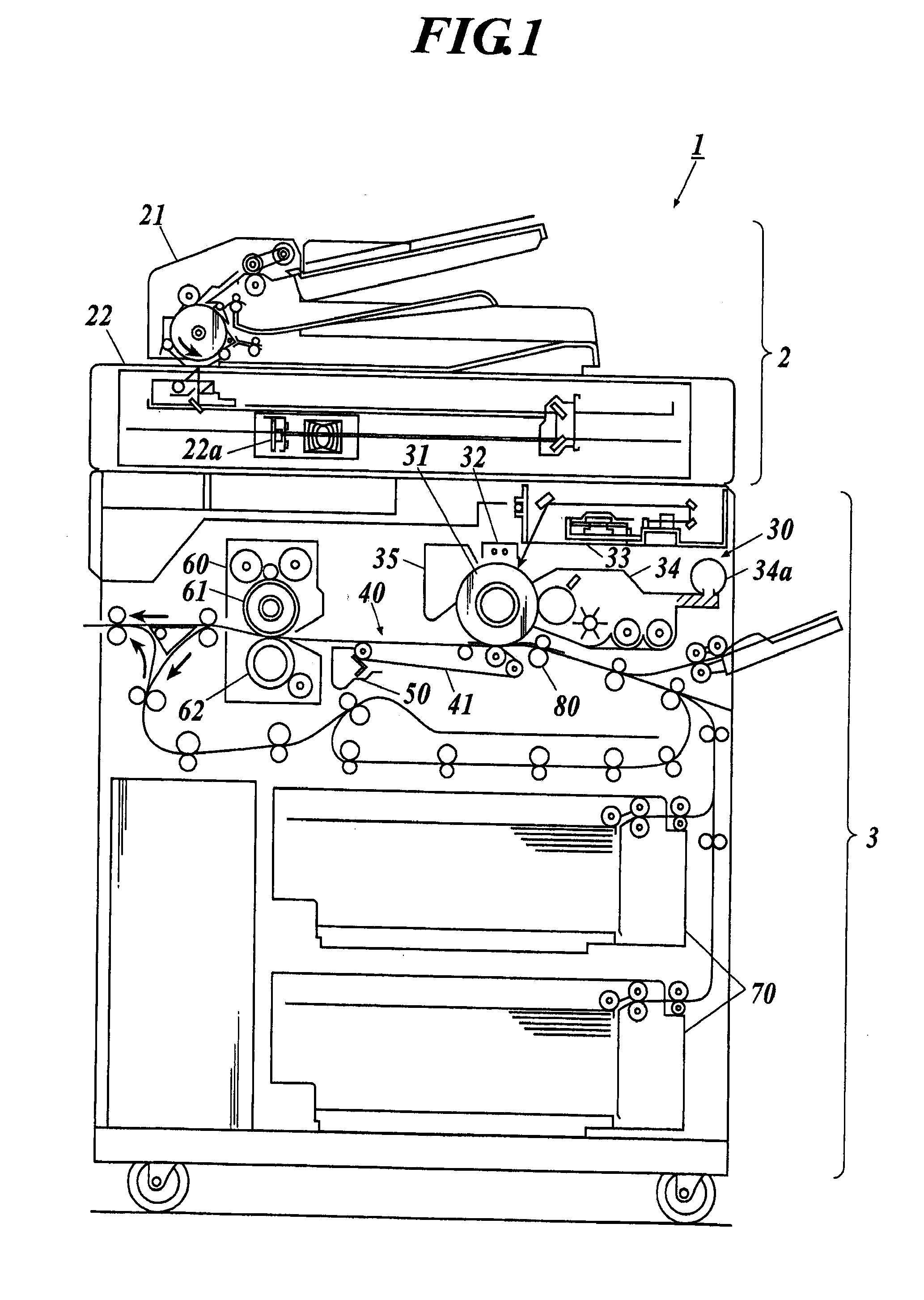
[0025]FIG. 1 shows the structure of an image forming apparatus according to an embodiment of the present invention.

[0026]An image forming apparatus 1 shown in FIG. 1 is a monochrome toner printer.

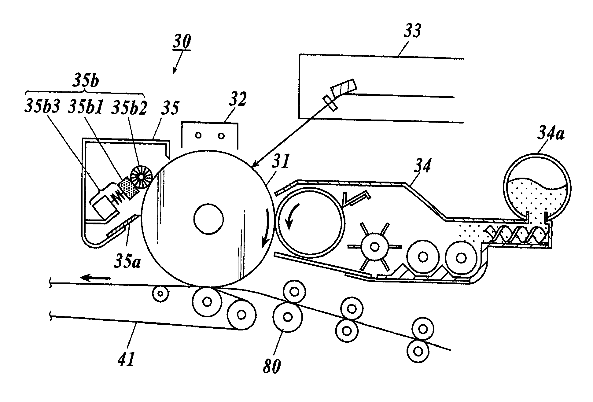
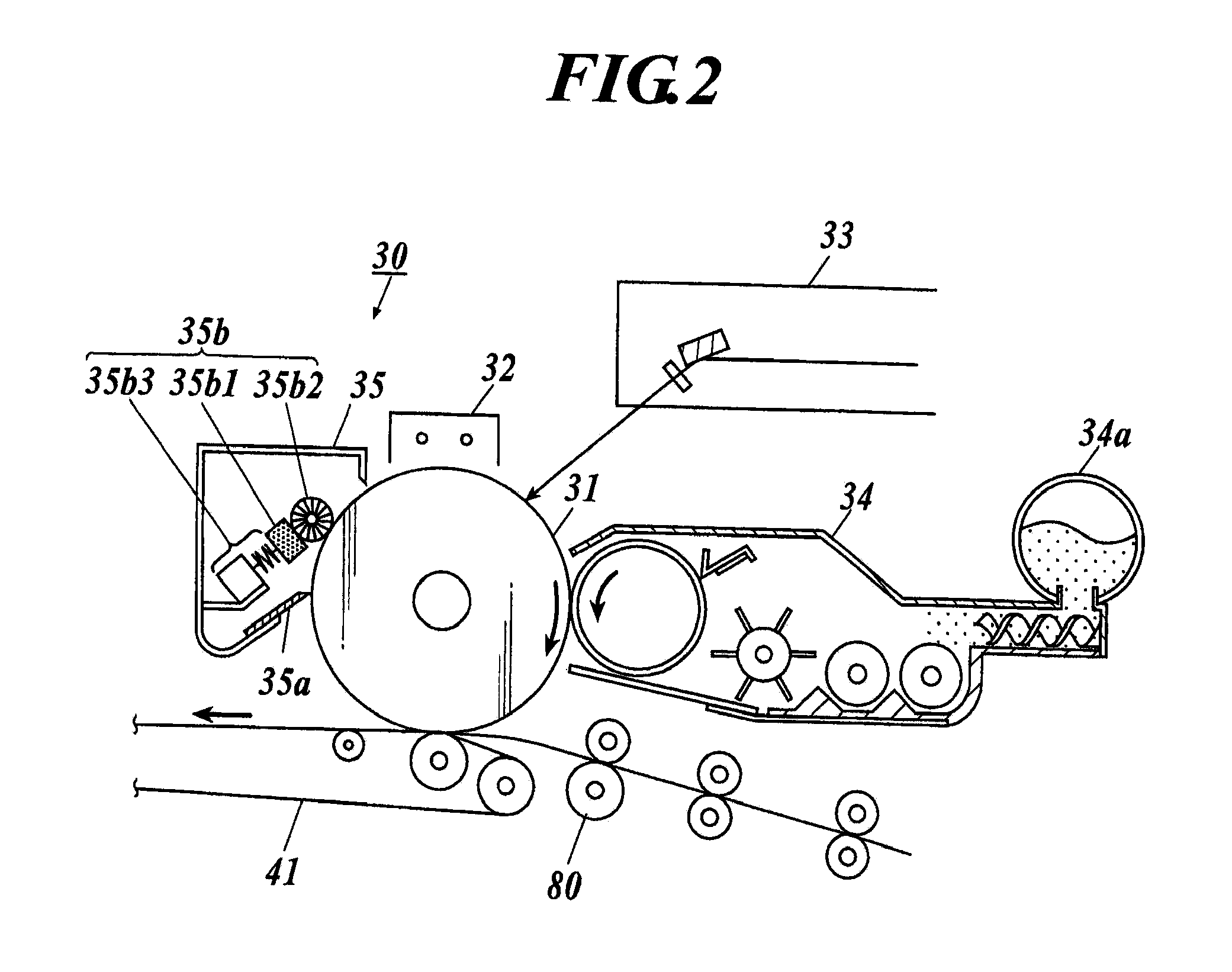
[0027]As shown in FIG. 1, the image forming apparatus 1 includes an image reading section 2 and a print section 3. The image reading section 2 includes an automatic document feeder 21 and a reading section 22. The print section 3 includes an image forming unit 30, a transfer unit 40, a cleaning unit 50, a fixation device 60, a paper feeding unit 70, and a register roller 80.

[0028]The automatic document feeder 21 is disposed at the upper part of the image forming apparatus 1. The automatic document feeder 21 includes a plurality of carrying rollers, thereby carrying ...


PUM


Abstract

An image forming apparatus includes: an image holder on which a toner image is formed; a lubricant applying section which applies a lubricant to the image holder; a torque calculation section which calculates torque of a drive motor which drives the image holder; a cleaning section which cleans the image holder; and a control section which calculates a print rate of the toner image formed on the image holder, makes determination of an adhering lubricant amount of the lubricant adhering to the image holder based on the print rate and the torque, and forms a toner image of a toner forcibly-discharging-pattern or increases an applied lubricant amount of the lubricant applied to the image holder by the lubricant applying section according to the determination.

Description

BACKGROUND OF THE INVENTION[0001]1. Field of the Invention[0002]The present invention relates to an image forming apparatus and a cleaning method.[0003]2. Description of the Related Art[0004]In an electrophotographic image forming apparatus, a cleaning blade or the like slides on the surface of an image holder (photosensitive drum, for example) so as to abut the surface thereof, thereby removing external matters such as the remaining toner adhering to the surface of the image holder (i.e. cleaning the surface of the image holder).[0005]To clean the image holder by the cleaning blade or the like, a technology is used, the technology by which a lubricant is applied to the surface of the image holder so that the lubricant adheres thereto, adhesive force of the toner to the image holder is reduced, and accordingly, cleaning performance of the image forming apparatus is improved.[0006]It is also known that the amount of the lubricant adhering (adhering lubricant amount) to the surface of...

Claims


Application Information

Patent Timeline
Patent Type & Authority Applications(United States)
IPC IPC(8): G03G15/00
CPCG03G15/757G03G21/007G03G21/0094G03G2221/1609G03G2215/00075
Inventor KIMURA, TAKENOBUSHOUNO, JUNPEI
Owner KONICA MINOLTA BUSINESS TECH INC
Learn More