
Multiple wavelength raman laser

a laser and multi-wavelength technology, applied in the field of lasers, can solve the problem of limited wavelengths that can be produced by nonlinear optical wavelength conversion

Active Publication Date: 2011-11-03
IPG PHOTONICS CORP
View PDF11 Cites 20 Cited by
  • Summary
  • Abstract
  • Description
  • Claims
  • Application Information

AI Technical Summary

Problems solved by technology

The wavelengths that can be produced by nonlinear optical wavelength conversion are limited however by the wavelengths that can be produced with available lasers and the nonlinear optical wavelength conversion processes.

Method used


Image

  • Multiple wavelength raman laser
  • Multiple wavelength raman laser
  • Multiple wavelength raman laser

Examples


Embodiment Construction

Glossary

[0016]As used herein:

[0017]Cavity or Optically Resonant Cavity refers to an optical path defined by two or more reflecting surfaces along which light can reciprocate or circulate. Objects that intersect the optical path are said to be within the cavity.

[0018]Chirping refers to a rapid change as opposed to a long-term drift in the emission wavelength of an optical source.

[0019]Continuous wave (CW) laser refers to a laser that emits radiation continuously rather than in short bursts, as in a pulsed laser.

[0020]Duty Cycle (D) refers to the product of the pulse duration τ and the pulse repetition frequency (PRF) for pulses that occur at regular intervals. The duty cycle may be expressed as a ratio, for example, 0.01 or equivalently may be expressed as a percentage, for example 1%.

[0021]Diode Laser refers to a light-emitting diode designed to use stimulated emission to generate a coherent light output. Diode lasers are also known as laser diodes or semiconductor lasers.

[0022]Diod...


PUM


Abstract

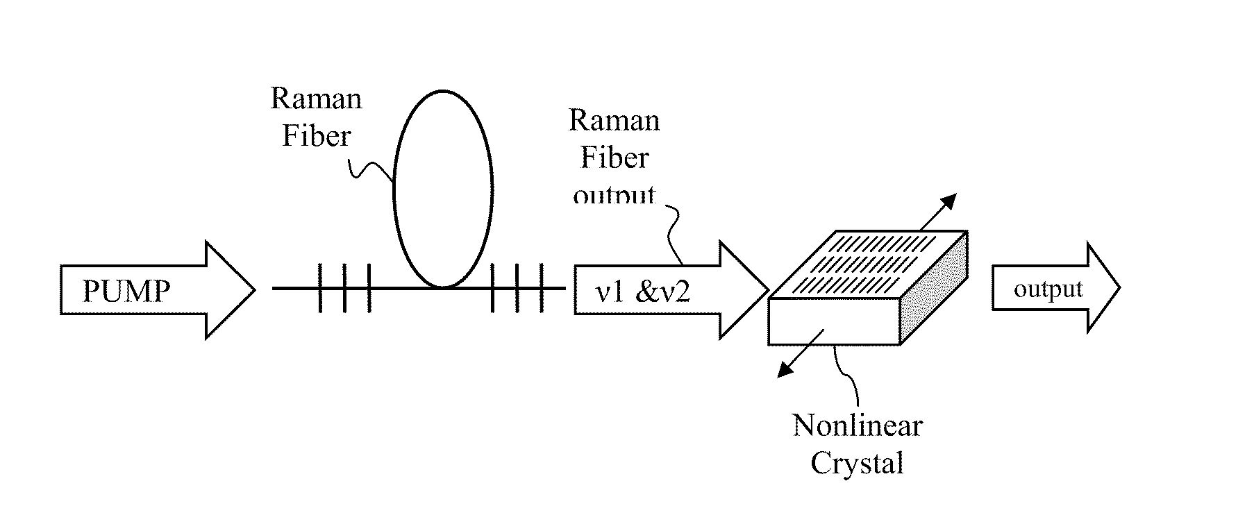
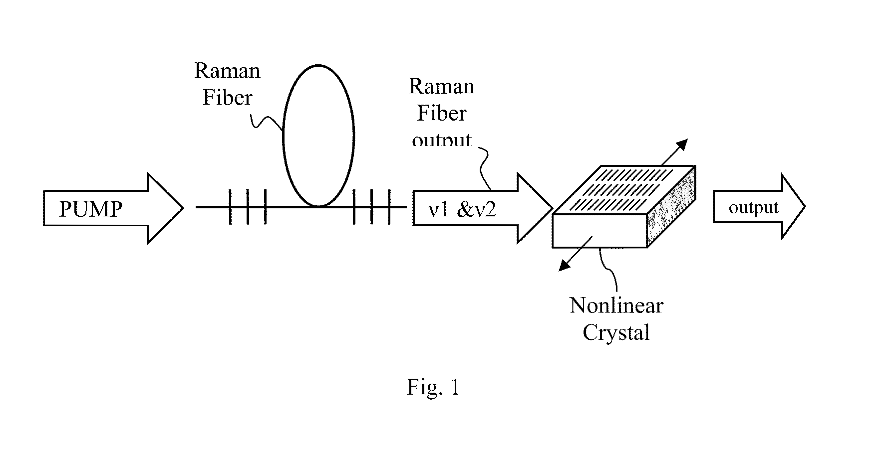
A pulsed laser system may include a Raman fiber that is configured to act as multiple wavelength Raman laser. The fiber is configured to receive a pulsed input beam from an input source and convert the input beam to an output beam having narrow band outputs at first and second frequencies v1 and v2.

Description

CLAIM OF PRIORITY[0001]This Application claims the priority benefit of co-pending U.S. Provisional Patent Application No. 61 / 326,534 filed Apr. 21, 2010, the entire contents of which are incorporated herein by reference.FIELD OF THE INVENTION[0002]Embodiments of the present invention are related to lasers and more specifically to multiple-wavelength Raman lasers.BACKGROUND OF THE INVENTION[0003]High-powered optical sources have many applications in which an intense beam of light is focused onto a substrate or other target. Many high power optical systems make use of wavelength conversion to produce light having a desired wavelength or range of wavelengths. Often the process of conversion involves performing some non-linear optical wavelength conversion on input light from a source, such as a laser. The wavelengths that can be produced by nonlinear optical wavelength conversion are limited however by the wavelengths that can be produced with available lasers and the nonlinear optical...

Claims


Application Information

Patent Timeline
IPC IPC(8): H01S3/30
CPCH01S3/0092H01S3/0675H01S3/06754H01S3/08086G02F2001/3548H01S3/2316H01S3/302G02F1/3532H01S3/09415G02F1/3548H01S3/094003H01S3/0941H01S3/1086H01S3/109
Inventor KEATON, GREGORY L.LEONARDO, MANUEL J.BYER, MARK W.MONRO, KIYOMI
Owner IPG PHOTONICS CORP
Learn More