
Systems and Methods For Hydraulic Barrier Formation To Improve Sweep Efficiency In Subterranean Oil Reservoirs

a technology of hydraulic barrier and oil reservoir, which is applied in the direction of fluid removal, fluid removal, borehole/well accessories, etc., can solve the problems of increased costs associated with drilling additional wells, difficulty in optimal placement of blocking agents, and difficulty in removing oil contained within the low permeability region of the reservoir without improvement of standard oil recovery techniques. , to achieve the effect of improving the efficiency of reservoir sweep and increasing the resistance to liquid flow

Inactive Publication Date: 2011-11-03
EXXONMOBIL UPSTREAM RES CO
View PDF6 Cites 18 Cited by
  • Summary
  • Abstract
  • Description
  • Claims
  • Application Information

AI Technical Summary

Benefits of technology

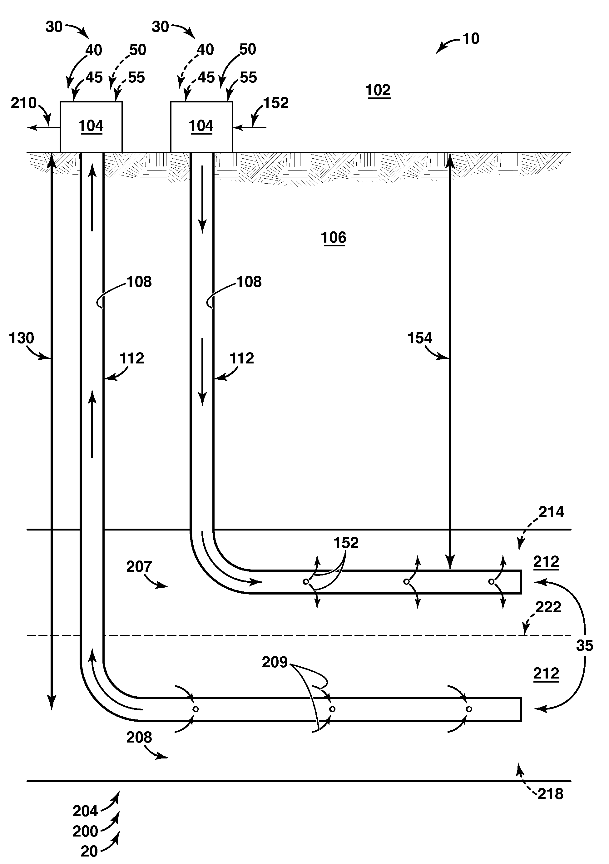
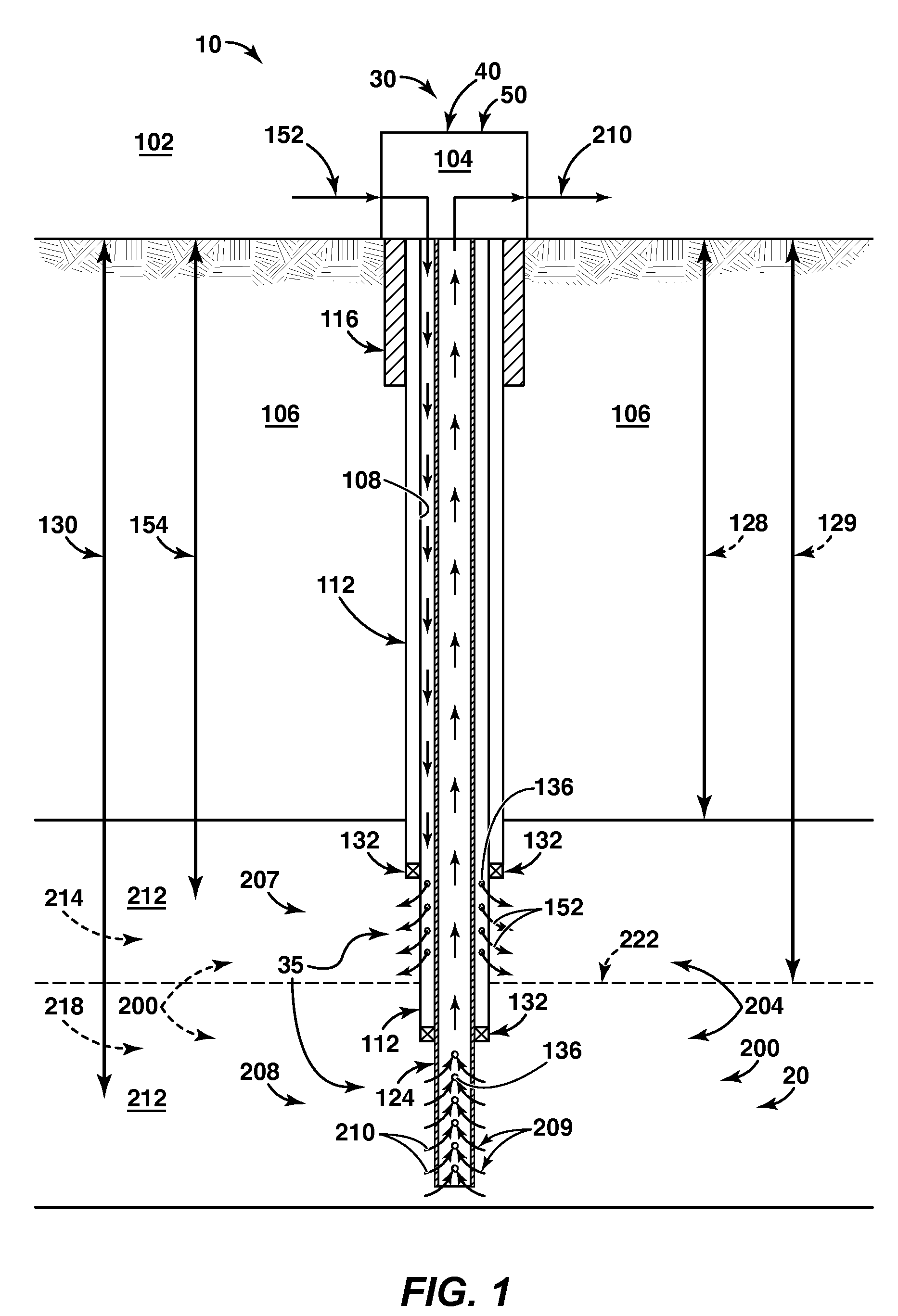
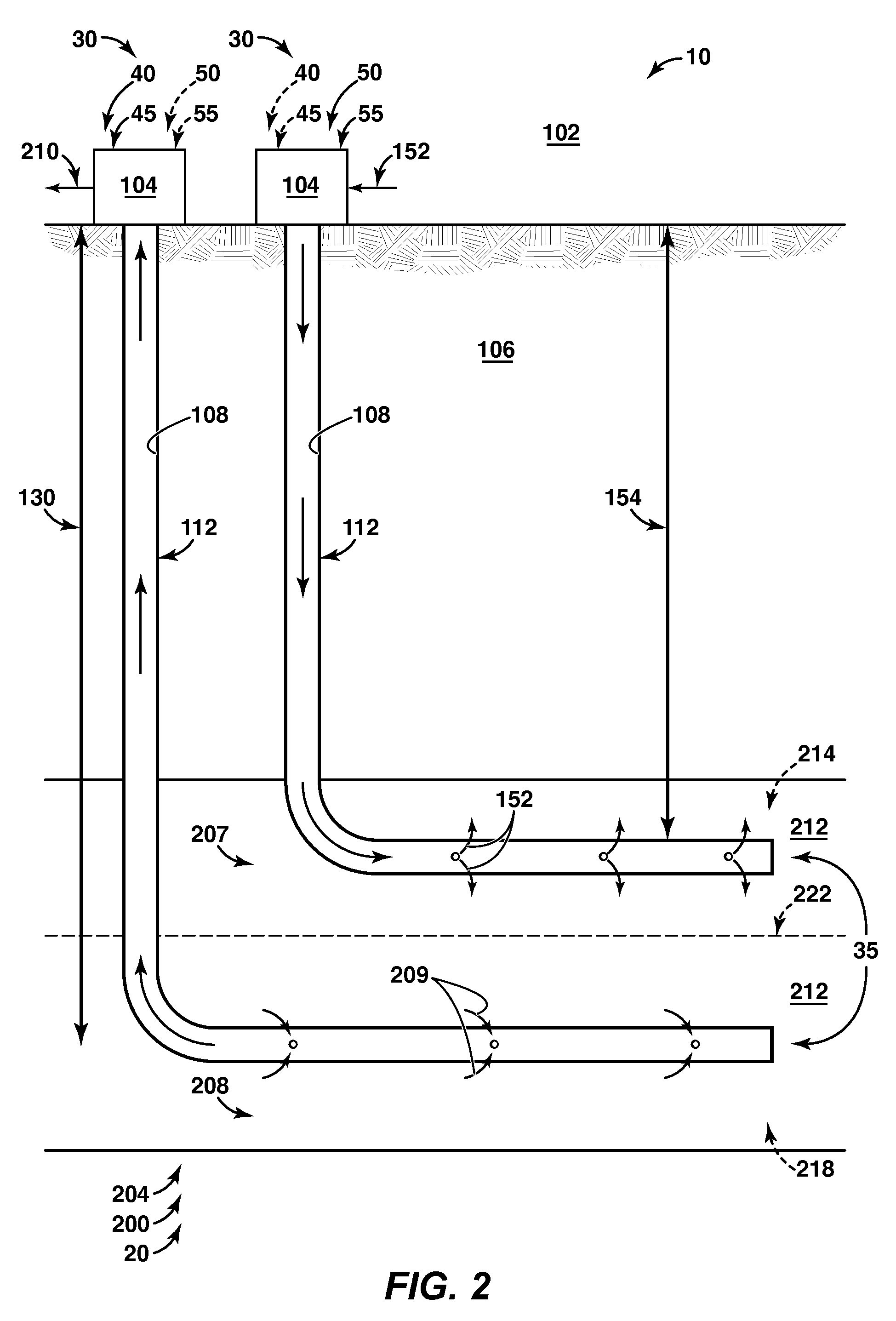
[0008]The present disclosure is directed to systems and methods for creating a hydraulic barrier between high and low permeability regions that may exist in a high permeability-contrast subsurface region, such as in a subterranean formation thereof. The systems and methods may include providing injection and / or production wells that may be completed within the high and / or low permeability regions. The subterranean formation may include an oil reservoir and the systems and methods may include producing oil from the oil reservoir. The hydraulic barriers may be created by supplying a solution or other mixture of injected fluid and a pore throat blocking agent to an interface between the high and low permeability regions and occluding fluid flow pores to increase resistance to liquid flow through the interface. The pore throat blocking agent may be sized to substantially flow through the high permeability region while being substantially blocked, or occluded, from the low permeability region. Formation of the barrier may improve reservoir sweep efficiency by systematically modifying the fluid flow path through the reservoir and / or by limiting bypass and / or channeling effects. The barrier also may isolate the high permeability regions from the low permeability regions and may enable them to be treated as separate formations and / or separate reservoirs, which may be swept independently. The barrier may be macroscopic and may cover one or more acres (0.40 hectare) in area. In some systems and / or methods according to the present disclosure, additional production and / or injection wells may be completed within the low permeability region after creation of the macroscopic barrier.

Problems solved by technology

Primary and secondary oil recovery techniques may be effective at removing the recoverable oil from the high permeability regions of the reservoir; however, it may be difficult to remove the oil contained within the low permeability regions of the reservoir without improvements to standard oil recovery techniques.
However, since pressurized fluids tend to flow along the path of least resistance, the presence of a high permeability region in fluid communication with a low permeability region, as is the case within high permeability-contrast subterranean reservoirs, may result in channeling of the injected and / or the produced fluids through the high permeability region.
However, the increased costs associated with drilling additional wells may be prohibitive.
In addition, unless the distance between the wells is relatively small, a significant percentage of the potentially recoverable oil may still remain within the low permeability region.
While these approaches may be effective under certain conditions, changing the bulk permeability of the high permeability region may require that a large mass of blocking agent be supplied to the subterranean reservoir.
Moreover, optimally placing the blocking agents may be difficult if the high permeability region covers a large area or is not immediately adjacent to a well.

Method used


Image

  • Systems and Methods For Hydraulic Barrier Formation To Improve Sweep Efficiency In Subterranean Oil Reservoirs
  • Systems and Methods For Hydraulic Barrier Formation To Improve Sweep Efficiency In Subterranean Oil Reservoirs
  • Systems and Methods For Hydraulic Barrier Formation To Improve Sweep Efficiency In Subterranean Oil Reservoirs

Examples


Embodiment Construction

[0018]The present disclosure is directed to systems and methods for creating a hydraulic barrier between high and low permeability regions that may exist in high permeability-contrast subterranean reservoirs of subsurface formations. As discussed in more detail herein, these systems and methods may include providing injection and / or production wells that are completed within the high and / or low permeability regions of the subterranean reservoir; supplying a pore throat blocking agent to an interface between the high and low permeability regions; and forming the hydraulic barrier at the interface between high and low permeability regions. As further discussed herein, the pore throat blocking agent may be sized to substantially flow through the high permeability region while being substantially blocked, or occluded, from the low permeability region.

[0019]In some embodiments, the subsurface formation may include a subterranean oil reservoir, and the systems and methods may include impr...


PUM


Abstract

Systems and methods for creating a hydraulic barrier at an interface between high and low permeability regions that may exist in high permeability-contrast subterranean formations. These systems and methods may include providing injection and / or production wells that are completed within the high and / or low permeability regions, supplying a pore throat blocking agent to an interface between the high and low permeability regions, and forming the hydraulic barrier at the interface. The pore throat blocking agent may be sized to substantially flow through the high permeability region while being substantially blocked, or occluded, from the low permeability region. In some embodiments, the hydraulic barrier may be greater than one acre (0.4 hectare) in area. In some embodiments, the subterranean formation may include an oil reservoir. In some embodiments, the high and / or low permeability formations may be swept concurrently and / or independently to remove oil from the oil reservoir.

Description

CROSS-REFERENCE TO RELATED APPLICATION[0001]The present application claims priority to and the benefit of U.S. Provisional Patent Application Ser. No. 61 / 330,037, which was filed on 30 Apr. 2010, which was entitled, SYSTEMS AND METHODS FOR HYDRAULIC BARRIER FORMATION TO IMPROVE SWEEP EFFICIENCY IN SUBTERRANEAN OIL RESERVOIRS, and which is incorporated herein by reference in its entirety for all purposes.FIELD OF THE DISCLOSURE[0002]The present disclosure is related generally to systems and methods for improving oil recovery from permeability-contrast subterranean oil reservoirs, and more particularly to such systems and methods that involve the creation of a hydraulic barrier at an interface between subterranean regions of different permeability.BACKGROUND OF THE DISCLOSURE[0003]Significant volumes of oil are known to exist in permeability-contrast subterranean reservoirs that include one or more high permeability regions adjacent to and / or in fluid communication with one or more lo...

Claims


Application Information

Patent Timeline
IPC IPC(8): E21B43/14
CPCC09K8/508E21B43/16E21B33/13
Inventor ENTCHEV, PAVLIN B.OWENS, III, DONALD E.KAMINSKY, ROBERT D.
Owner EXXONMOBIL UPSTREAM RES CO
Learn More