Eureka AIR delivers breakthrough ideas for toughest innovation challenges, trusted by R&D personnel around the world.

Method and apparatus for manufacturing an axle for a vehicle

a technology for axles and vehicles, applied in forging/pressing/hammering apparatuses, auxiliary welding devices, forging/hammering/pressing machines, etc., can solve problems such as metal fatigue, reducing the useful life of axles, and dislocation of spindles, so as to reduce costs

Active Publication Date: 2011-11-03
TRIMTOOL LTD
View PDF16 Cites 37 Cited by
  • Summary
  • Abstract
  • Description
  • Claims
  • Application Information

AI Technical Summary

Benefits of technology

[0009]It is a further object of the present invention to provide a method and apparatus for manufacturing an axle that does not require machine finishing of the spindles and flanges after assembly.
[0010]It is a further object of the present invention to provide a method and apparatus for manufacturing an axle having precise alignment between the brake flanges and the spindles.
[0011]It is a further object of the present invention to provide a method and apparatus for manufacturing an axle having reduced cost.

Problems solved by technology

While this process is adequate for producing axles, it has a number of drawbacks.
The multiple welding operations impart a large quantity of heat to the parts, resulting in distortion and possible misalignment of the spindles 20 and flanges 22.
However, the straightening operation causes metal fatigue and reduces the useful lifetime of the axle 10.
While this produces a satisfactory alignment between the parts, it is difficult to manipulate the fully-assembled axle in order to machine the spindles 20 and flanges 22, due to the large size and weight of the assembled axle 10.
In particular, the mass of the cover is offset from the longitudinal axis of the axle 10, and causes the axle 10 to be unbalanced, making it even more difficult to manipulate and machine.
In addition, machining a part as large as an assembled axle 10 requires a large amount of floor space, particularly when several machining operations are performed at several different stations within the assembly area, and the assembled axle is machined in a horizontal orientation, resulting in a high cost of manufacture.
In addition, machining a large part requires large and expensive machinery, further adding to the cost of manufacture.
In addition, the added machining required to finish the spindles 20 and flanges 22 after the axle 10 is assembled results in increased manufacturing time, further increasing the cost of manufacture.

Method used


Image

  • Method and apparatus for manufacturing an axle for a vehicle
  • Method and apparatus for manufacturing an axle for a vehicle
  • Method and apparatus for manufacturing an axle for a vehicle

Examples


first embodiment

[0084]Referring to FIGS. 9A-9E, an apparatus 900 for welding the spindles 20 to the axle sub-assembly 406 will now be described according to a

[0085]Referring to FIG. 9C, the apparatus 900 consists of a welding machine 902, a turntable 904 and a robotic arm 903, all mounted to a platform 901 such that their coordinates relative to each other are fixed.

[0086]Referring to FIG. 9A, the turntable 904 includes a jig 905 extending along the length of the turntable 904. The jig 905 is adapted to receive and hold the axle sub-assembly 406 in a precise position relative to the datums 404. The jig 905 is mounted to tracks 914 also extending along the length of the turntable 904 that allow the axle sub-assembly 406 to be moved back and forth along its longitudinal axis 916. It is contemplated that the jig 905 may alternately be fixed in position, in which case the welding machine 902 would be mounted to tracks to allow the welding machine 902 to move back and forth along the axis 920. The jig 9...

second embodiment

[0092]Referring to FIG. 9F, the jig 905 is fixed in position. Two welding machines 902 are provided at opposite ends of the jig 905, facing respective ends 18, 19 of the axle sub-assembly 406 when the axle sub-assembly 406 is received and held in the jig 905. The welding machines 902 are mounted on respective tracks 950 similar to the tracks 914 of FIGS. 9A-9E, and movable along the axis 916 via an endless screw (not shown) similar to the endless screw 944 of FIG. 9E. The welding machines 902 each receive a finished spindle 20, and the welding machines 902 are then moved along the tracks 950 toward the respective ends 18, 19 of the axle sub-assembly 406 until each clamping bracket 906 abuts against the wall 940 of the respective welding machine 902, ensuring precise alignment between the finished spindle 20 and the brake flange 22. Both spindles 20 are simultaneously welded to the axle sub-assembly 406 by rotation about the spin welding axis 920, similarly to the manner described a...


PUM

PropertyMeasurementUnit
Timeaaaaaaaaaa
Angleaaaaaaaaaa

Abstract

A datum is created in an axle housing. A finished brake flange is welded to the axle housing with reference to the datum to make an axle sub-assembly. The axle sub-assembly is fixed to a first part of a machine. A finished spindle is supplied to a second part of the machine. The spindle is welded to the axle sub-assembly with reference to the datum. A dial indexing table is rotated to a first position. An axle is placed on the dial indexing table with its longitudinal axis oriented vertically. The dial indexing table is rotated to a second position, wherein the axle aligned with a CNC machine. A machining operation is performed on the axle with the CNC machine. The dial indexing table is rotated to a third position. The axle is removed from the dial indexing table. An axle and an apparatus for manufacturing an axle are described.

Description

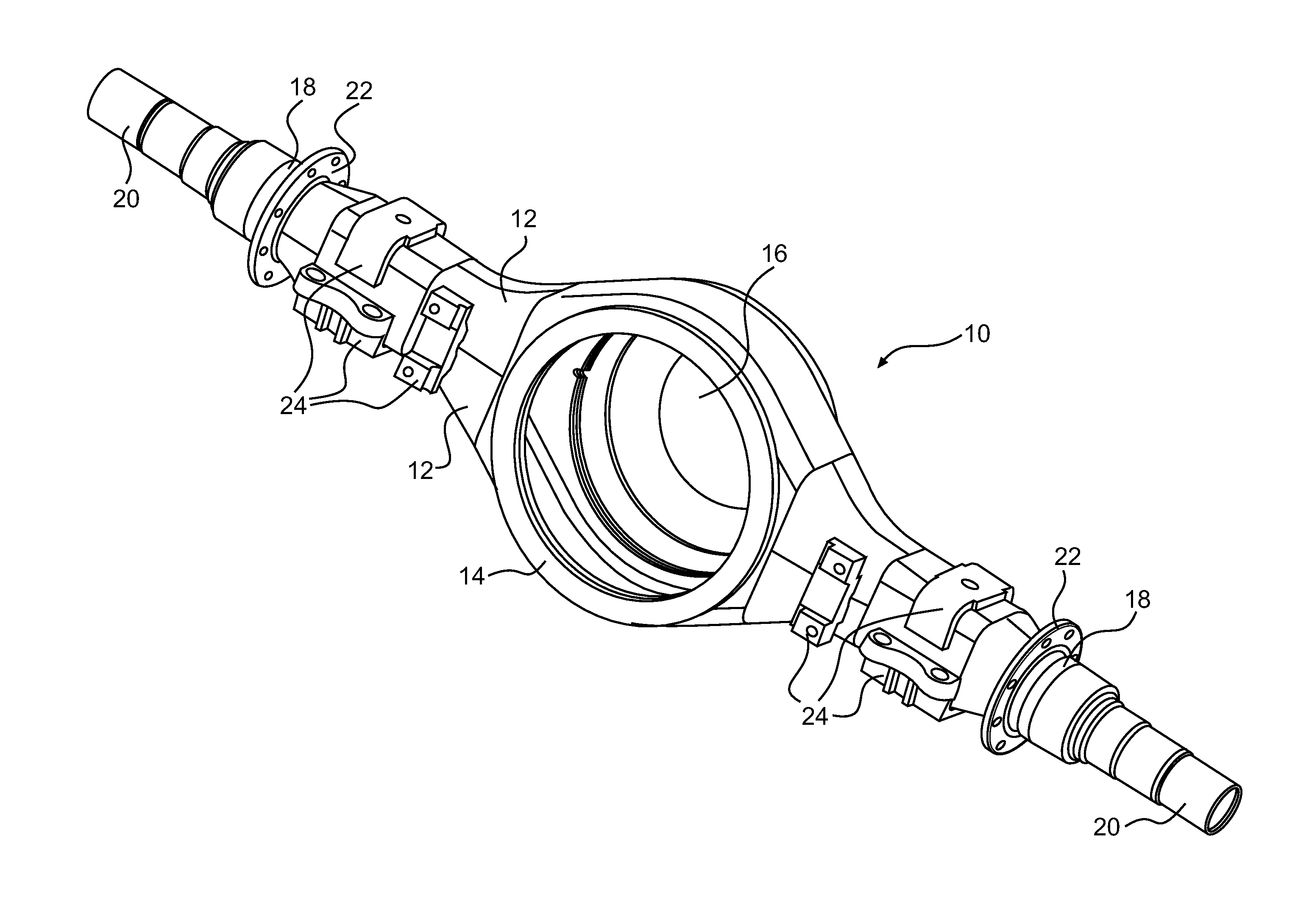
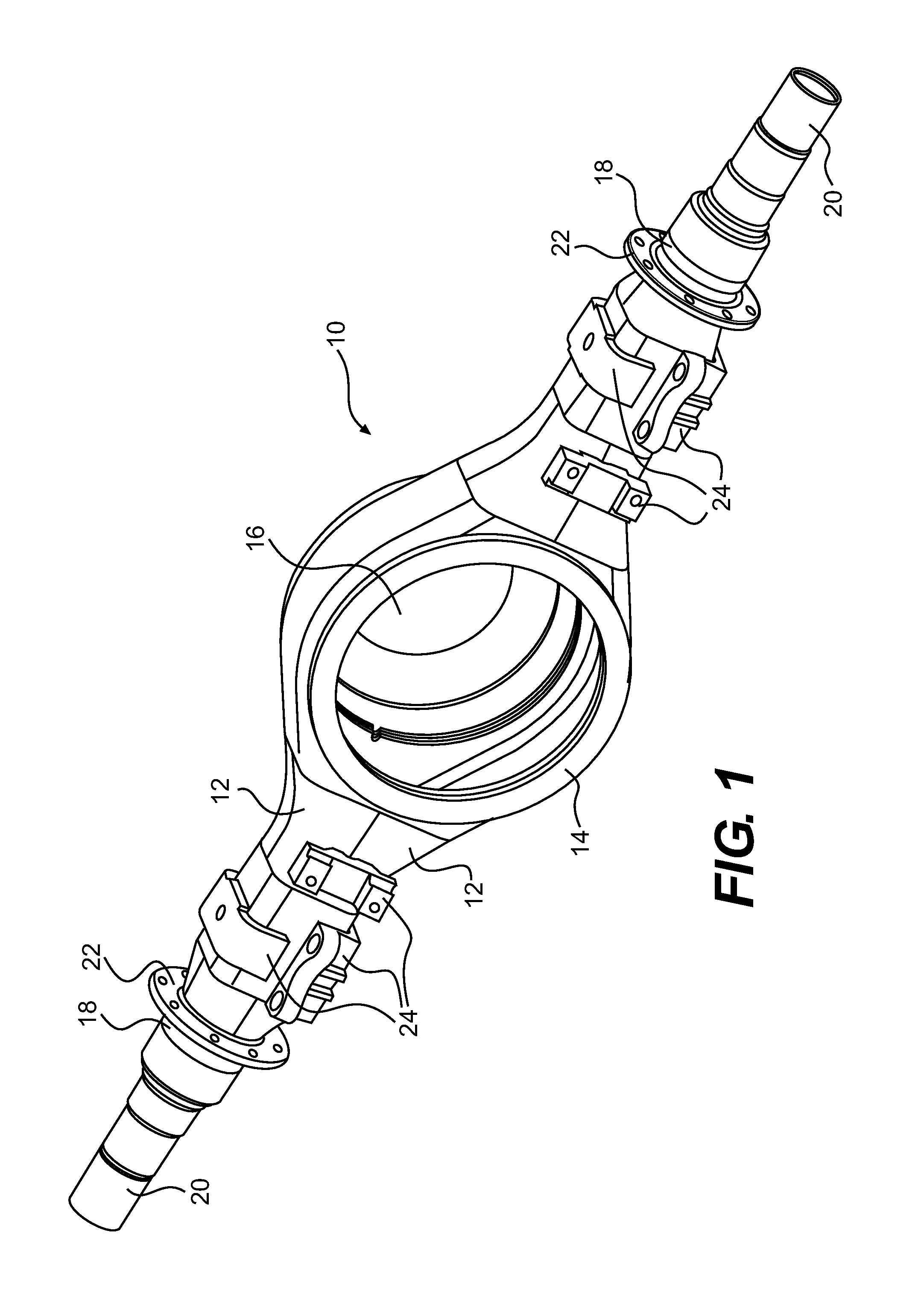
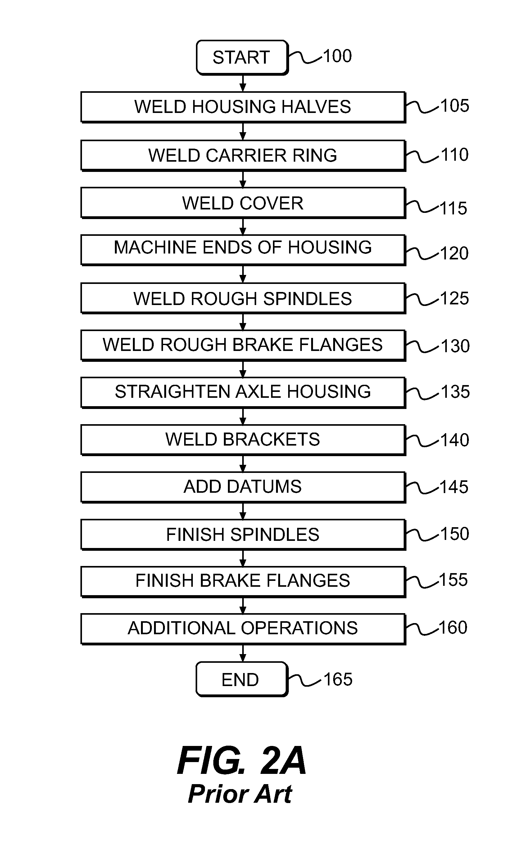
FIELD OF THE INVENTION[0001]The present invention relates to a method and apparatus for manufacturing an axle for a vehicle.BACKGROUND OF THE INVENTION[0002]Referring to FIG. 1, an axle 10 for a truck or other vehicle is typically assembled in a series of welding and machining steps shown in FIG. 2A, beginning at step 100. At step 105, two housing halves 12 are welded together to form an axle housing. At step 110, a carrier ring 14 is welded to the housing. At step 115, a cover 16 is welded to the housing. At step 120, the ends 18 of the axle housing are machined. At step 125, rough spindles 20 are welded to the machined ends 18. At step 130, rough brake flanges 22 are welded to the machined ends 18. At step 135, the axle housing is straightened, to compensate for any distortion that may have occurred during the various welding steps. At step 140, brackets 24 are welded to the axle housing. At step 145, the ring 14 is machined, including drilling one or more holes (not shown) that a...

Claims


Application Information

Patent Timeline
IPC IPC(8): B23P15/00B23P17/00B23P23/04B23P11/00
CPCY10T29/5176Y10T29/49622B23P15/00Y10T29/5183B60B35/12B60B35/16Y10T29/5165
Inventor JOHNSTON, CHRISTAVES, ROBERT
Owner TRIMTOOL LTD
Why Eureka
Eureka Blog
Learn More