Electrical connector

a technology of electrical connectors and connectors, applied in the direction of coupling devices, two-part coupling devices, electrical apparatus, etc., can solve the problems of reducing the electrical connection quality of electrical connectors, achieve the effect of reducing the number of components to be punched and electroplated, enhancing the tensile strength of electrical connectors, and reducing environmental pollution

Inactive Publication Date: 2011-10-27
CHEN WAN TIEN
View PDF3 Cites 1 Cited by
  • Summary
  • Abstract
  • Description
  • Claims
  • Application Information

AI Technical Summary

Benefits of technology

[0008]Another object of the present invention is to provide an electrical connector in which at least one reverse stab is installed on a buckling sheet, so when the buckling sheet is connected to an insulation housing, the reverse stab stabs in the insulation housing for preventing the buckling sheet from being separated from the insulation housing and the tensile strength thereof is enhanced.
[0009]Still another object of the present invention is to provide an electrical connector capable of reducing components to be punched and electroplated so as to lower the environmental pollution.

Problems solved by technology

But the material of which the insulation housing of said conventional DIMM electrical connector is made is plastic material and the insulation housing is in an elongated shape, so when subject to high temperature environment during manufacturing or transporting, the insulation housing may be deformed and results in that heights of two sides of the insulation housing are different; in such condition, when the electrical connector, the plural first conductive terminals and the plural second conductive terminals are welded on a printed circuit board, false welding may occur due to the height difference, and the electrical connection quality of the electrical connector is lowed.

Method used


Image

  • Electrical connector
  • Electrical connector
  • Electrical connector

Examples


Embodiment Construction

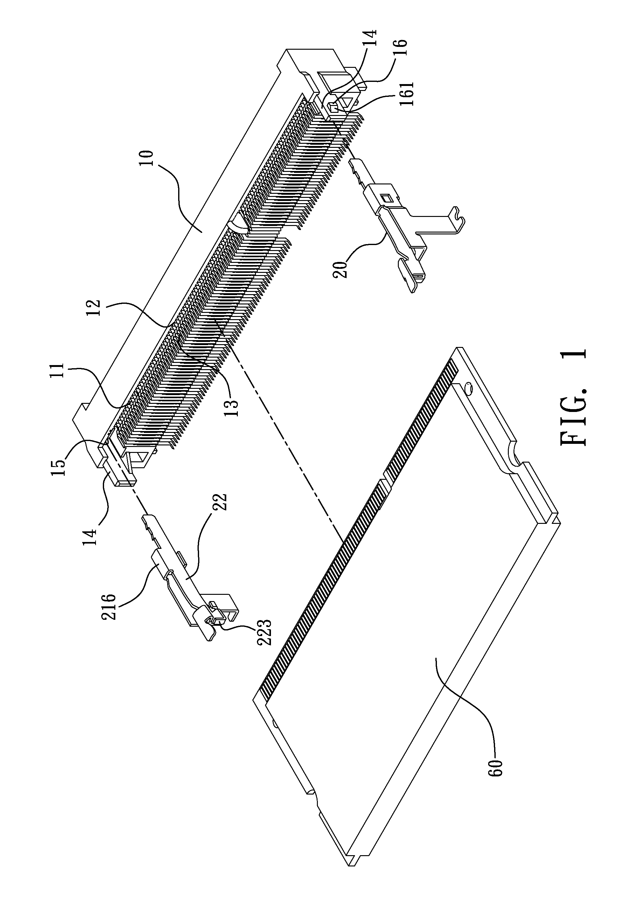
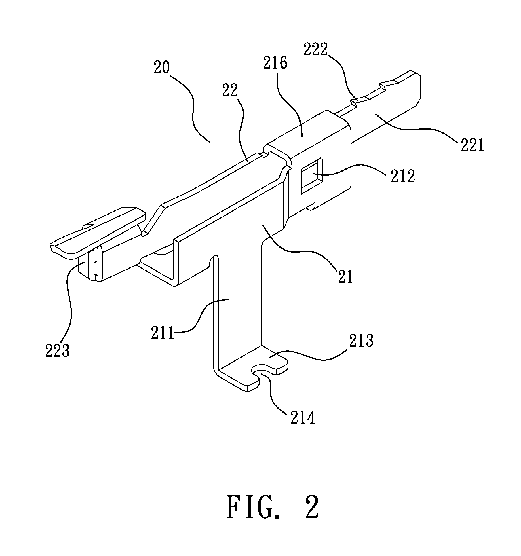
[0015]Referring from FIG. 1 to FIG. 4, wherein FIG. 1 is a schematic exploded view of the electrical connector of one preferred embodiment of the present invention; FIG. 2 is a schematic partially enlarged view of the buckling sheet of one preferred embodiment of the present invention; FIG. 3 is a schematic front view of the assembly of the electrical connector of one preferred embodiment of the present invention; and FIG. 4 is a schematic view illustrating the electrical connector of one preferred embodiment of the present invention being connected with an electrical card.

[0016]As shown in figures, the electrical connector provided by the present invention comprises: an insulation housing 10; and a buckling sheet 20.

[0017]The insulation housing 10 is made of, e.g. but not limited to, plastic material, and is installed with an insertion slot 11 for receiving an electrical card 60, the insertion slot 11 is provided with a plurality of first conductive terminals 12 and a plurality of ...


PUM


Abstract

The present invention relates to an electrical connector, comprises: an insulation housing of which two sides are respectively installed with an arm portion, the inner side of each arm portion is provided with a slot hole, the outer side thereof has a latching block; and a buckling sheet having a first sheet member and a second sheet member, the right side of the first sheet member has a latching hole, and one side of the second sheet member is installed with a wing sheet, when the wing sheet is inserted in the slot hole, the latching block is latched in the latching hole, and a slit is defined at the top or bottom end of the latching block and the latching hole, such that the fastening sheet is able to be firmly welded on a substrate through adjusting the longitudinal location of the latching block inside the latching hole.

Description

BACKGROUND OF THE INVENTION[0001]1. Field of the Invention[0002]The present invention relates to an electrical connector, especially to an electrical connector in which a fastening sheet is integrated with a buckling sheet and capable of being firmly welded on a substrate through longitudinally adjusting the location of the buckling sheet.[0003]2. Description of Related Art[0004]The package means of memory module mostly are: single in-line memory module (SIMM) or dual in-line memory module (DIMM), wherein the width of data bits of the SIMM is 32 bits while the width of data bits of the DIMM is 64 bits. So one DIMM can process the same amount of data as two SIMMs are capable of, Thus the DIMM is the main stream in the memory module field.[0005]A conventional DIMM electrical connector is often installed with an insulation housing having an insertion slot for receiving a memory module, the insertion slot is installed with a plurality of first conductive terminals and a plurality of sec...

Claims


Application Information

Patent Timeline
Patent Type & Authority Applications(United States)
IPC IPC(8): H01R24/00
CPCH01R12/721H01R12/7029
Inventor CHEN, WAN-TIEN
Owner CHEN WAN TIEN
Why Eureka
Try Eureka