Image Forming Apparatus

Inactive Publication Date: 2011-10-27
BROTHER KOGYO KK
View PDF3 Cites 0 Cited by
  • Summary
  • Abstract
  • Description
  • Claims
  • Application Information

AI Technical Summary

Benefits of technology

The present invention has been devised for resolving the problem in the conventional image forming apparatus described above. That is, an object of the present invention is to provide an image forming apparatus in which occasions that a mark used for adjusting an image forming section is formed are reduced so that useless consumption of consumable supplies is controlled.
That is, in the printing of FAX data, high image quality is seldom required. Thus, the acquisition processing seldom provides an advantage. Accordingly, in the image forming apparatus according to the present invention, when a FAX reception request is received in a state that the execution condition for acquisition processing is satisfied, at the time of negotiation for establishing the communication, function information concerning the function of the image forming means is replied to the sender of the FAX reception request. In accordance with this, the sender does not transmit FAX data serving as a trigger for execution of the acquisition processing. As a result, the acquisition processing is not executed. That is, the number of times of execution of acquisition processing (i.e., the number of times of formation of a mark that causes consumption of colorant) is reduced.
According to the present invention, an image forming apparatus is realized in which occasions that a mark used for adjusting the image forming means is formed are reduced so that useless consumption of consumable supplies is controlled.

Problems solved by technology

Nevertheless, the conventional image forming apparatus described above has a problem as follows.
Then, such frequent mark formation causes useless consumption of consumable supplies.

Method used


Image

  • Image Forming Apparatus
  • Image Forming Apparatus
  • Image Forming Apparatus

Examples


first embodiment

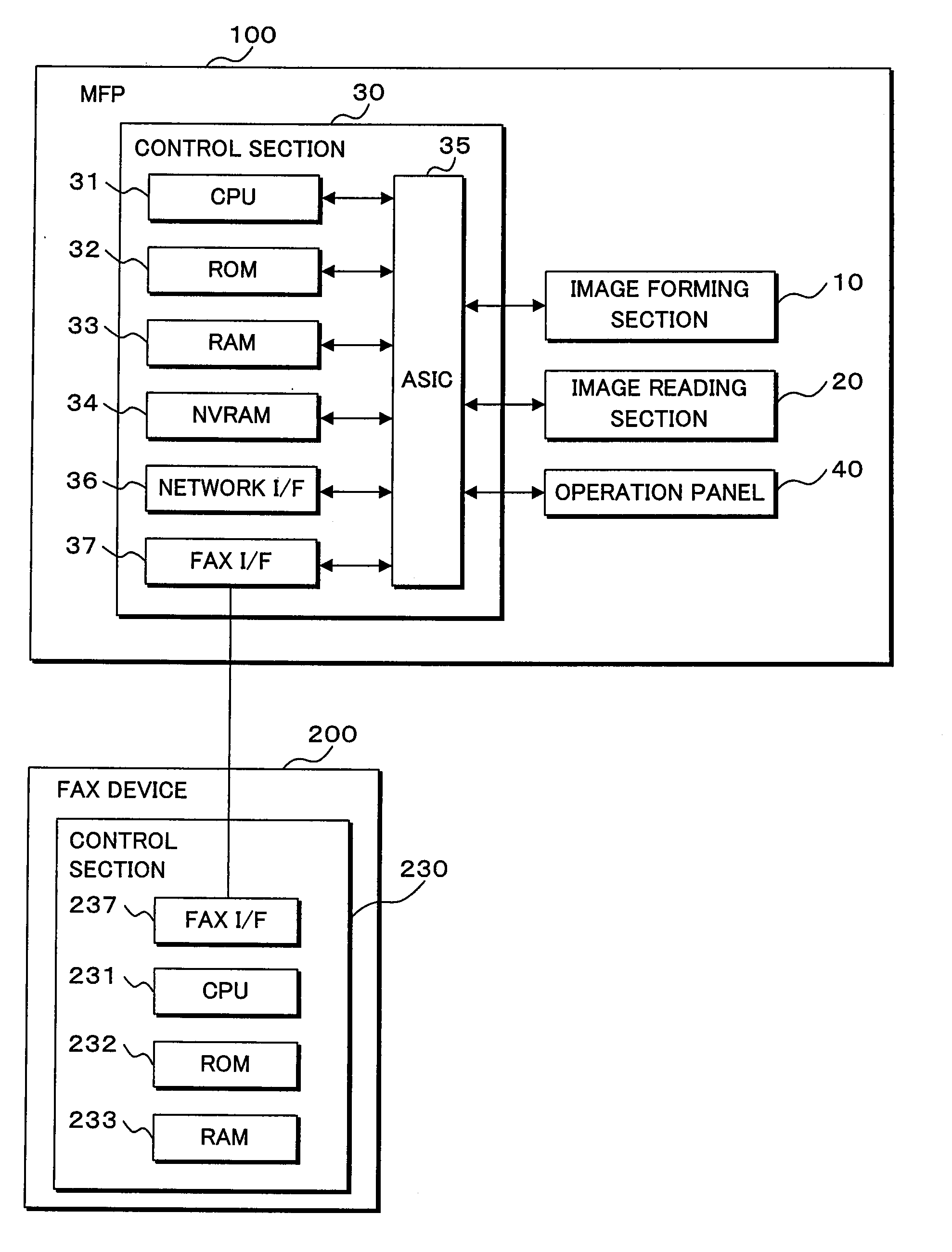
Next, a procedure of printing FAX data is described below for a system constructed from a FAX device 200 serving as a transmitting-side apparatus and an MFP 100 serving as a receiving-side apparatus.

[FAX Transmission Processing]

First, FAX transmission processing in the FAX device 200 (an example of conversion means, receiving means, and transmitting means) is described below with reference to the flow chart of FIG. 5. The FAX transmission processing is executed when a FAX transmission request is received.

First, the FAX device 200 (a transmitting-side apparatus) places a call to the MFP 100 (a receiving-side apparatus) (S001). Then, after the line is connected between the FAX device 200 and the MFP 100, the FAX device 200 acquires the function information of the MFP 100 through the FAX interface 237 (S002). The function information contains at least information indicating whether color printing is available. In addition, the function information may contain, for example, the resoluti...

second embodiment

Next, a second embodiment of FAX data printing is described below. The MFP 100 according to the second embodiment has a “batch printing mode” that when FAX data is received in a state that the correction value update flag is ON, the received FAX data is stored into the memory, and then in response to a trigger defined as the update of correction values (that is, execution of acquisition processing) performed later, the FAX data stored in the memory is printed collectively. The batch printing mode is capable of being selected by a user. Then, information on the selected batch printing mode is stored as mode information in the memory of the MFP 100.

[FAX Receiving Processing]

FAX receiving processing (an example of the second storage means) of an MFP having a batch printing mode is described below with reference to the flow chart of FIG. 8. Here, processing steps like those of the FAX receiving processing according to the first embodiment are designated by like numerals. Further, the FA...


PUM


Abstract

An MFP has: a receiving section receiving a FAX reception request and FAX data; and an image forming section capable of forming a color image. When an execution condition for acquisition processing of acquiring information used for adjusting the image forming section is satisfied, the MFP executes the acquisition processing in response to a trigger defined as start or end of processing of a print job. Further, when receiving a FAX reception request in a state that the execution condition for acquisition processing is satisfied, the MFP notifies function information concerning the function of the image forming section (e.g., information indicating that color image formation is not available), to a FAX device of sender.

Description

CROSS-REFERENCE TO RELATED APPLICATIONSThis non-provisional application claims priority under 35 U.S.C. §119(a) on Patent Application No. 2010-097487 filed in Japan on Apr. 21.2010, the entire contents of which are hereby incorporated by reference.TECHNICAL FIELDThe present invention relates to an image forming apparatus in which a mark used for adjusting an image forming section is formed and then based on a correction value acquired by detecting the mark, the image forming section is adjusted and, in particular, to an image forming apparatus having a receiving section receiving a FAX reception request and FAX data and an image forming section capable of forming a color image.BACKGROUNDIn the prior art, in an image forming apparatus, the image forming section is adjusted such that deviation should not arise in the position or the density of an image. As a procedure of adjusting the image forming section, for example, first, a registration pattern serving as a mark used for adjustin...

Claims


Application Information

Patent Timeline
IPC IPC(8): G06F3/12
CPCH04N2201/33378G03G15/0194H04N1/00015H04N1/00023H04N1/00031H04N1/00053H04N1/00063H04N1/00087H04N1/32673H04N1/33307H04N1/33384H04N2201/0093H04N2201/0094G03G15/5058G03G2215/00059
Inventor HANAYAMA, YUKIYOSHI
Owner BROTHER KOGYO KK
Why Eureka
Try Eureka