
Optical touch screen system and method for recognizing a relative distance of objects

Inactive Publication Date: 2011-10-27
SUNPLUS INNOVATION TECH
View PDF18 Cites 22 Cited by
  • Summary
  • Abstract
  • Description
  • Claims
  • Application Information

AI Technical Summary

Benefits of technology

[0014]The object of the present invention is to provide an optical touch screen system, which can accurately filter out ghost points and effectively increase the accuracy of multi-point touching.

Problems solved by technology

Accordingly, the touch position obtained by such method is not accurate.
When the ghost points cannot be canceled, it makes an error in recognition.
For example, a left rotation of gesture may be erroneously determined as a right rotation to thereby negatively affect the optical touching accuracy.
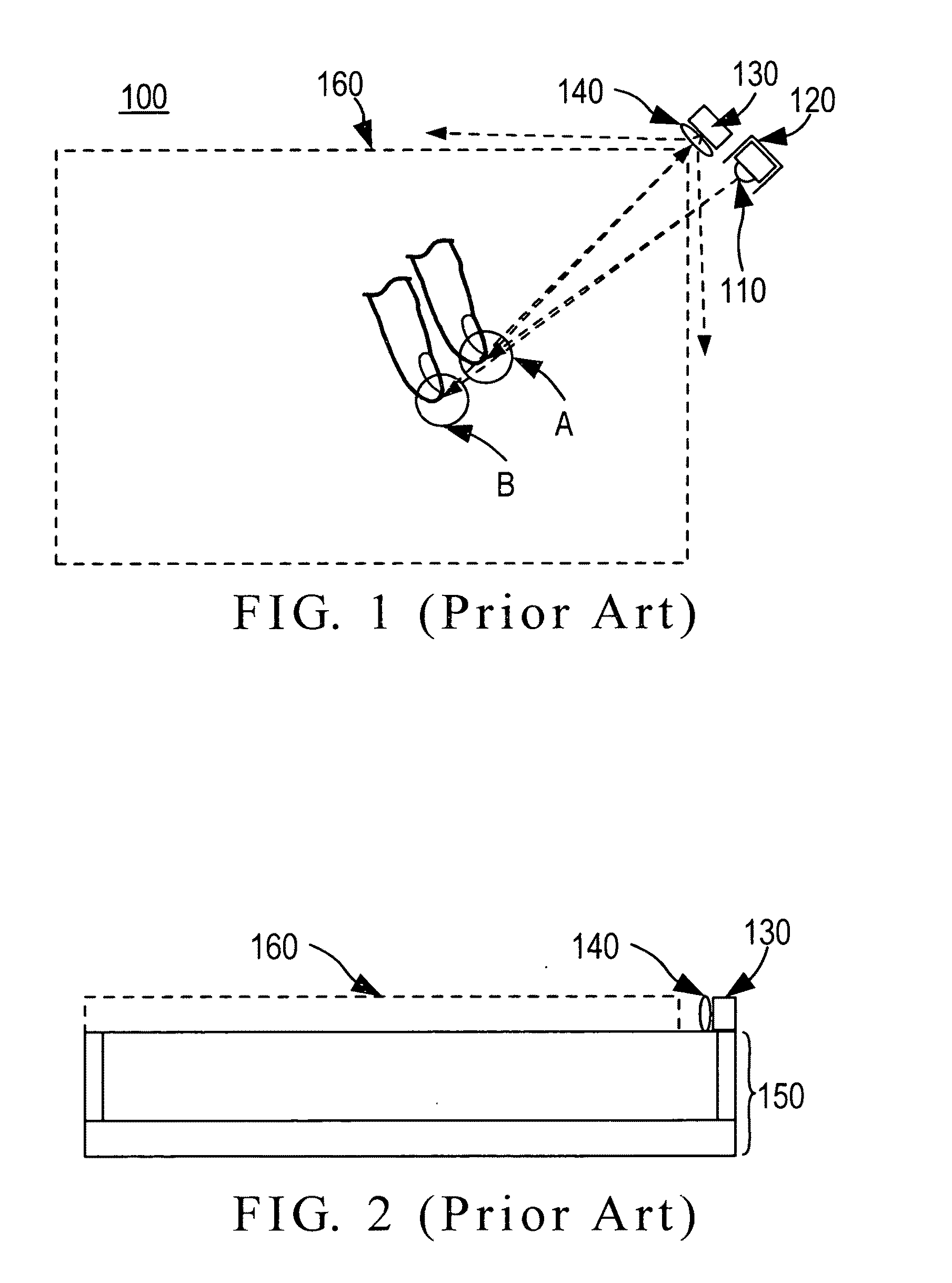
In the subsequent processes, the ghost point recognition method includes: (1) determining a width by using a sensed image to decide the width of light beam generated by a reflective light and using the width ratio to decide the distance of a touching object, which has a disadvantage of easily making a wrong decision when the touching object has a uniform width or an overlarge width error at different angles, for example, the wrong decision occurs when the width error of a finger at different angles is over 20%; (2) brightness level distribution and statistics, i.e., the distance of the object is determined by analyzing the ratio of grey scale to the maximum brightness since the grey scale effect is generated as the touching object reflects a light, wherein the error increases as the object's surface radian increases; and (3) adjusting the optical sensor into an inclined top visual direction such that its image presents a solid effect to thereby decide the distance of the object, but due to the inclination, an interference may be caused by a reflective light source when the light is reflected onto the surface.

Method used


Image

  • Optical touch screen system and method for recognizing a relative distance of objects
  • Optical touch screen system and method for recognizing a relative distance of objects
  • Optical touch screen system and method for recognizing a relative distance of objects

Examples


Embodiment Construction

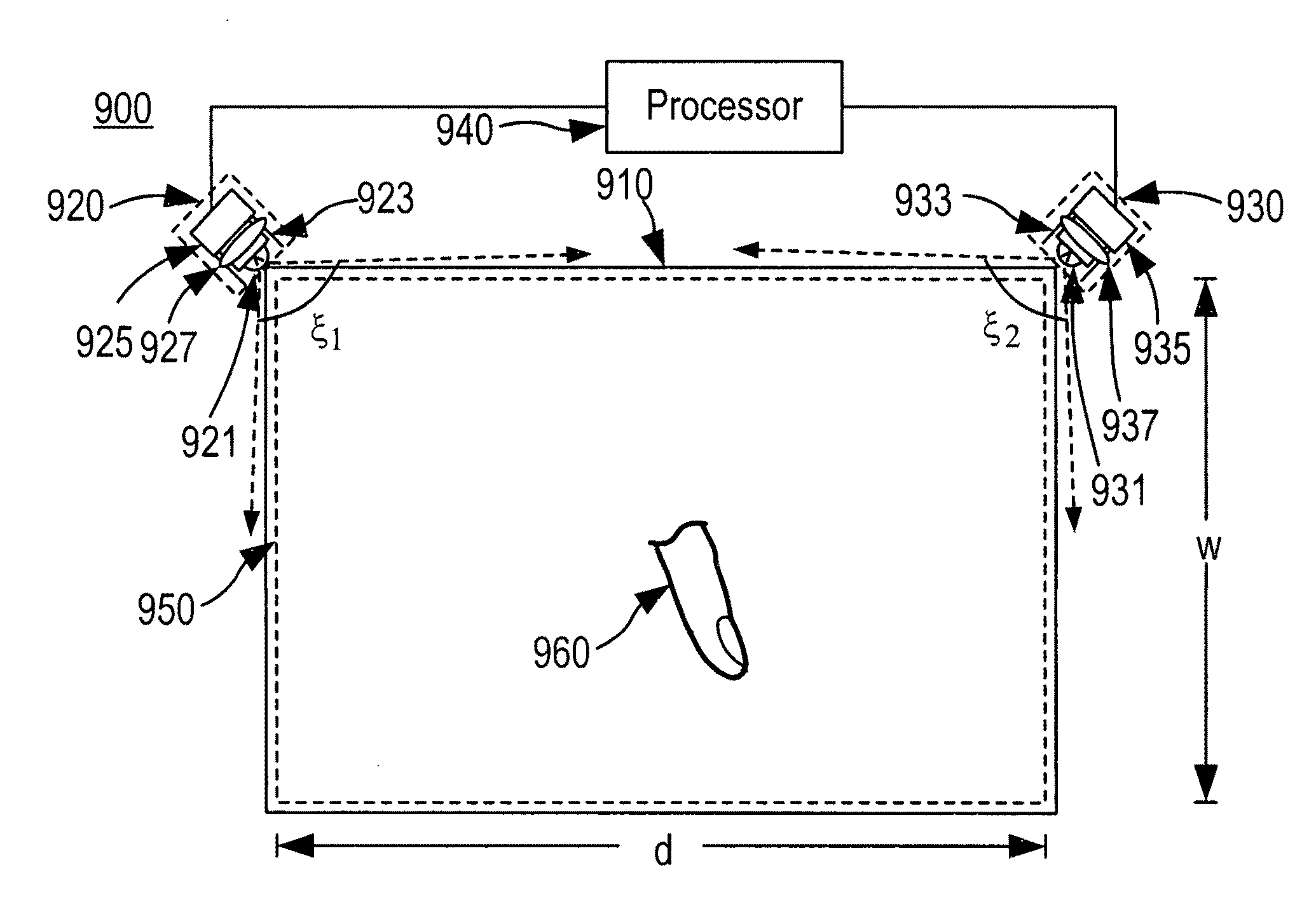
[0033]FIG. 9 is a schematic view of an optical touch screen system 900 according to an embodiment of the invention. The system 900 includes a display screen 910, a first lighting and sensing module 920, a second lighting and sensing module 930, and a processor 940.

[0034]The display screen 910 displays visual prompts to users in order to further control the human-machine interface. In this embodiment, the display screen 910 is preferably an LCD. The operation principle of the optical touch screen system 900 according to the invention can be implemented on various screens without any affection. Thus, the display screen 910 can be a CRT, LED, or plasma display screen.

[0035]The first lighting and sensing module 920 and the second lighting and sensing module 930 are mounted at two adjacent corners of the display screen 910 to thereby form a first visual field ξ1 and a second visual field ξ2 above the display screen 910, respectively. The first visual field ξ1 and the second visual field ...


PUM


Abstract

An optical touch screen system for recognizing a relative distance of an object based on optical sensors includes a display screen to display visual prompts to solicit actions from a user; first and second lighting and sensing modules mounted on two adjacent corners of the display screen for forming first and second visual fields above the display screen respectively, wherein the first and the second visual fields intersect to form a touch area on the display screen, and the first and the second lighting and sensing modules detect an object entering the touch area and generate a first electrical position signal and a second electrical position signal respectively; and a processor for calculating a position of the object based on the first electrical position signal and the second electrical position signal.

Description

BACKGROUND OF THE INVENTION[0001]1. Field of the Invention[0002]The present invention relates to the technical field of image processing and, more particularly, to an optical touch screen system and method for recognizing relative distance of objects.[0003]2. Description of Related Art[0004]Currently, touch screens (i.e., touch panels) are in widespread use for being directly touched by an object or a finger to perform an operation instead of a mechanical button operation. When a user touches a picture on a screen, a sensing feedback system implemented on the screen can drive the connectors based on the pre-programmed codes, and the screen can present colorful audiovisual effects to completely control a human-machine interface.[0005]There are several types of touch screens available in the market, which are resistive touch screen, capacitive touch screen, acoustic touch screen, and optical touch screen. The optical touch screen uses an optical sensor to receive a reflective light to...

Claims


Application Information

Patent Timeline
IPC IPC(8): G06F3/042
CPCG06F3/0428G06F2203/04104G06F2203/04101
Inventor HUANG, CHUN-WEI
Owner SUNPLUS INNOVATION TECH
Learn More