
Electronic visual displays

a visual display and electronic technology, applied in the field of electronic visual displays, can solve the problems of insufficient timeframe for human conscious decision, inability to display two-dimensional images, and inability to rapidly detect by pre-adjustment processing

Active Publication Date: 2011-10-13
APTIV TECH LTD
View PDF5 Cites 48 Cited by
  • Summary
  • Abstract
  • Description
  • Claims
  • Application Information

AI Technical Summary

Benefits of technology

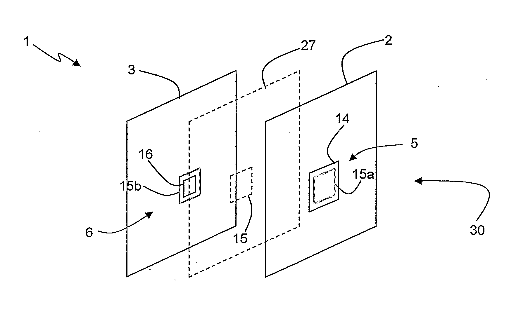
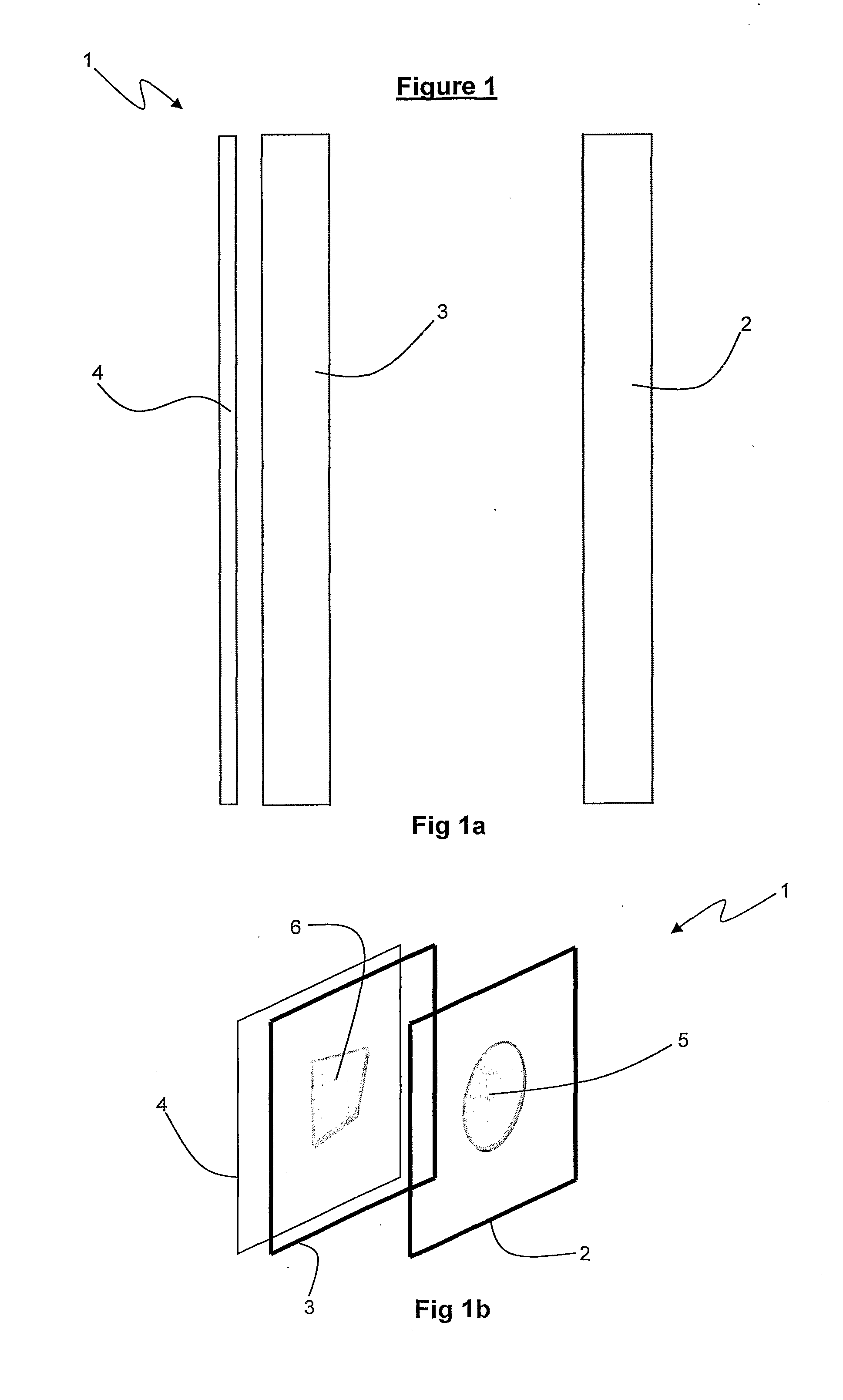
Reference herein to an MLD having two display layers should not be seen to be limiting as the principles of the present invention may be easily extrapolated for display on an MLD with three or more display layers.
The alteration identification algorithm thus provides a means for ‘background’ monitoring any image property alterations without requiring modification of the images or code of the software applications displayed
The aforementioned methods, computer software and systems thus provide a means for simultaneously altering synchronised images on multiple display layers when only one of the images is altered, thereby obviating the need to alter each image on each display layer individually.
Preferably, the split-ratio depth map is generated by creating a visual representation of the image property split-ratio and wherein said image property is one or more of pixel intensity, colour, contrast, brightness, hue or other image property capable of visually representing a scale of split-ratio values. The split-ratio depth map (“or split-ratio image”) can thus be generated in common 2D image editing tools and thereby obviates the need for many of the complex MLD image-editing tools.
Varying the pixel intensity of overlapping portions of the first and second images according to the present invention enables a composite image to be displayed which is perceived by the viewer as being distributed between the display layers with portions at some point intermediate, on, in front of or behind the display layers depending on the split-ratio as assigned by the depth map. While the images are displayed only on the display layers, the human visual system perceives a 3D volumetric image as there is a smooth intensity gradient between the front and rear portions.

Problems solved by technology

However, most display technologies are generally only capable of displaying two-dimensional images on a single screen.
When viewing a large number of visual elements, certain variations or properties in the visual characteristics of elements can lead to rapid detection by preattentive processing.
This timeframe is insufficient for a human to consciously decide to look at a different portion of the scene.
However, if the target is composed of a conjunction of unique features, i.e. a conjoin search, then research shows that these may not be detected preattentively.
Using the above examples, if a target is included for example, of a red circle set within distractors including blue circles and red squares, it is not possible to detect the red circle preattentively as all the distractors include one of the two unique features of the target.
In comparison, if the constituent elements of the above described cubes are re-orientated to remove the apparent three dimensionality, subjects cannot preattentively detect targets which have been inverted for example.
Unfortunately, each of these possesses certain limitations.
Head-mounted displays add ergonomic inconvenience, reduce the viewer's peripheral awareness and are often cumbersome and can cause nausea, headaches and / or disorientation.
Lenticular displays are only really effective at oblique viewing angles and holography is currently limited to displaying static images.
The passive matrix system has significant drawbacks, notably slow response time and imprecise voltage control.
Imprecise voltage control hinders the passive matrix's ability to influence only one pixel at a time.
When voltage is applied to untwist one pixel, the pixels around it also partially untwist, which makes images appear fuzzy and lacking in contrast.
However, existing computer operating systems, computer graphic controllers and software have to date not been optimised or configured for volumetric displays such as the aforementioned MLD system.
There is no way to move or manipulate these two windows together with a single user action.
The manual repositioning requirement is clearly undesirable and hampers user operability.
This presents a problem if the developer does not want to lose context of the rest of their work space for example, or the content development environment and GUI.
This creates a number of time consuming steps, including creation of different image layers or sets and arranging the image layers so that they are synchronised.
However, creating a realistic 3D representation can be a difficult and time consuming task, even for experienced 3D artists.
2D images do not normally contain 3D data and thus cannot be readily adapted to an MLD without substantial work generating the depth data.
Current image editing software is also not designed to operate in multiple display layers of an MLD.
This can be an extremely time consuming and error-prone method as the assigning of images to front and rear layers is normally completed in a 2D workspace with the front and rear image pairs being positioned in adjacent windows in the workspace on a double wide window.
Acceptable results may only be obtained after several attempts in aligning the images, increasing the time required and therefore the cost of MLD content generation.
One of the main problems with developing 3D content with existing 2D editing software is that there is no automated way to synchronise related images to be displayed on different display layers so that they move and alter together as they are edited.

Method used


Image

  • Electronic visual displays
  • Electronic visual displays
  • Electronic visual displays

Examples


Embodiment Construction

Reference will now be made in detail to embodiments of the present invention, examples of which are illustrated in the accompanying drawings. While the present invention will be discussed in conjunction with the following embodiments, it will be understood that they are not intended to limit the present invention to these embodiments alone. On the contrary, the present invention is intended to cover alternatives, modifications, and equivalents which may be included within the spirit and scope of the present invention as defined by the appended claims. Furthermore, in the following detailed description of the present invention, numerous specific details are set forth in order to provide a thorough understanding of the present invention. However, embodiments of the present invention may be practiced without these specific details. In other instances, well-known methods, procedures, components, and circuits have not been described in detail so as not to unnecessarily obscure aspects of...


PUM


Abstract

An improved method and / or system to generate depth data for a 2D image for subsequent display on an MLD or other volumetric display. A multi-layered display (MLD) includes first and second display layers with one said display layer overlapping the other said display layer. The first display layer displays a first image and a second display layer displays a second image. The second image is synchronised with said first image such that an alteration of at least one image property of said first age triggers an alteration of at least one image property of said second image.

Description

FIELD OF THE INVENTIONThe invention relates to improvements in and relating to electronic visual displays and in particular to improved methods, systems and computer software for generating images on multi-focal plane displays.BACKGROUNDElectronic display technology for displaying graphical images and / or text has evolved dramatically to meet the pervasive user demand for more realistic and interactive displays. A wide range of display technologies with differing capabilities are now available including:Cathode Ray Tube (CRT)Bistable displayElectronic paperNixie tube displaysVector displayFlat panel displayVacuum fluorescent display (VF)Light-emitting diode (LED) displaysElectroluminescent Displays (ELD)Plasma display panels (POP)Liquid crystal display (LCD)High-Performance Addressing (HPA)Thin-film transistor displays (TFT)Organic light-emitting diode displays (OLED)Surface-conduction electron-emitter display (SED) (experimental)Laser TV (forthcoming)Carbon nanotubes (experimental)N...

Claims


Application Information

Patent Timeline
Patent Type & Authority Applications(United States)
IPC IPC(8): G09G5/00H04N13/395
CPCG02F1/1347G09G3/003G09G2300/023G09G2340/0464H04N13/0497G09G3/36H04N13/0495H04N13/398H04N13/395
Inventor SINGH, DARRYL
Owner APTIV TECH LTD
Learn More