Touch Sensitive Image Display

Inactive Publication Date: 2011-10-13
PROMETHEAN
View PDF4 Cites 209 Cited by
  • Summary
  • Abstract
  • Description
  • Claims
  • Application Information

AI Technical Summary

Benefits of technology

[0023]Advantageously, an embodiment of the first aspect may allow a reduction in the number of components required for a touch sensitive image display device. This may be the case where the projection multiplexing is in the time domain so that, e.g., the light sources may be the same light source, i.e., a single light source is used to project both distributions. Similarly, this may be the case where light of different wavelengths obtained from a single broadband light source is used to project both distributions. This may be achieved using filters.
[0062]When the display device is in use, the second light distribution may be above the first light distribution. Compared to the case where they are on the same level, this may be advantageous in avoiding any need to perform a touch to initiate an action (e.g., to wake the device up or an element of the touch sensing system such as the light source for the first light distribution). Preferably, the first light distribution is very close to the surface where the image is displayed, for example less than about 3 mm above the surface. The first distribution is advantageously sufficiently close to the surface that the user feels that the device is controllable by touching rather than by merely positioning an object in the first distribution. The second distribution may be about 1 to about 2 cm above the first distribution.

Problems solved by technology

Table down projection is not readily achievable by conventional image display techniques; scanning image display systems have a narrow throw angle and thus find it difficult to achieve a useful image size whilst projection systems, especially those based on LEDs (light emitting diodes) which have a wide light output angle, find it difficult to achieve a useful depth of field.
Moreover table down projection can often involve very substantial distortion of an image which can result in inefficient use of the area of an image display device, resulting in major reductions in image brightness and overall system efficiency.

Method used


Image

  • Touch Sensitive Image Display
  • Touch Sensitive Image Display
  • Touch Sensitive Image Display

Examples


Embodiment Construction

[0088]This invention generally relates to a touch sensitive display device and to a consumer electronic device comprising such a device.

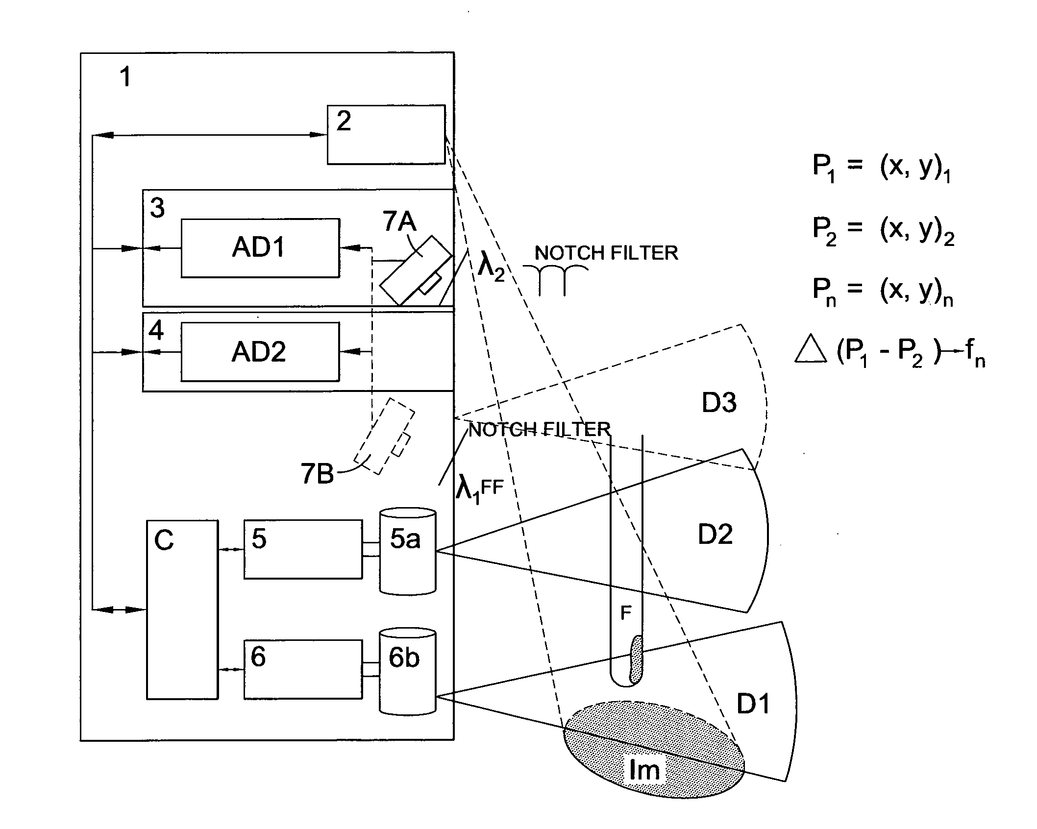
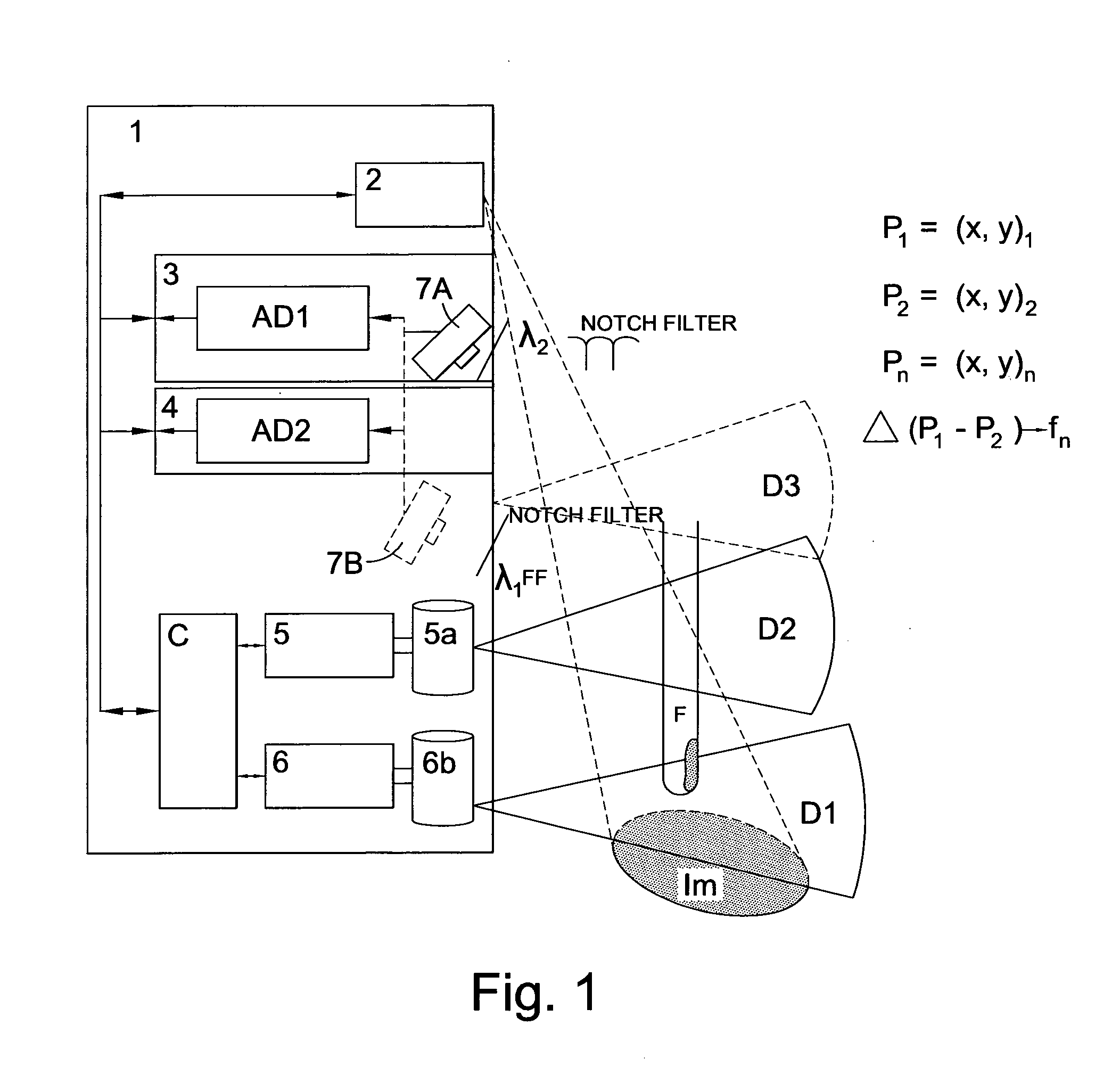
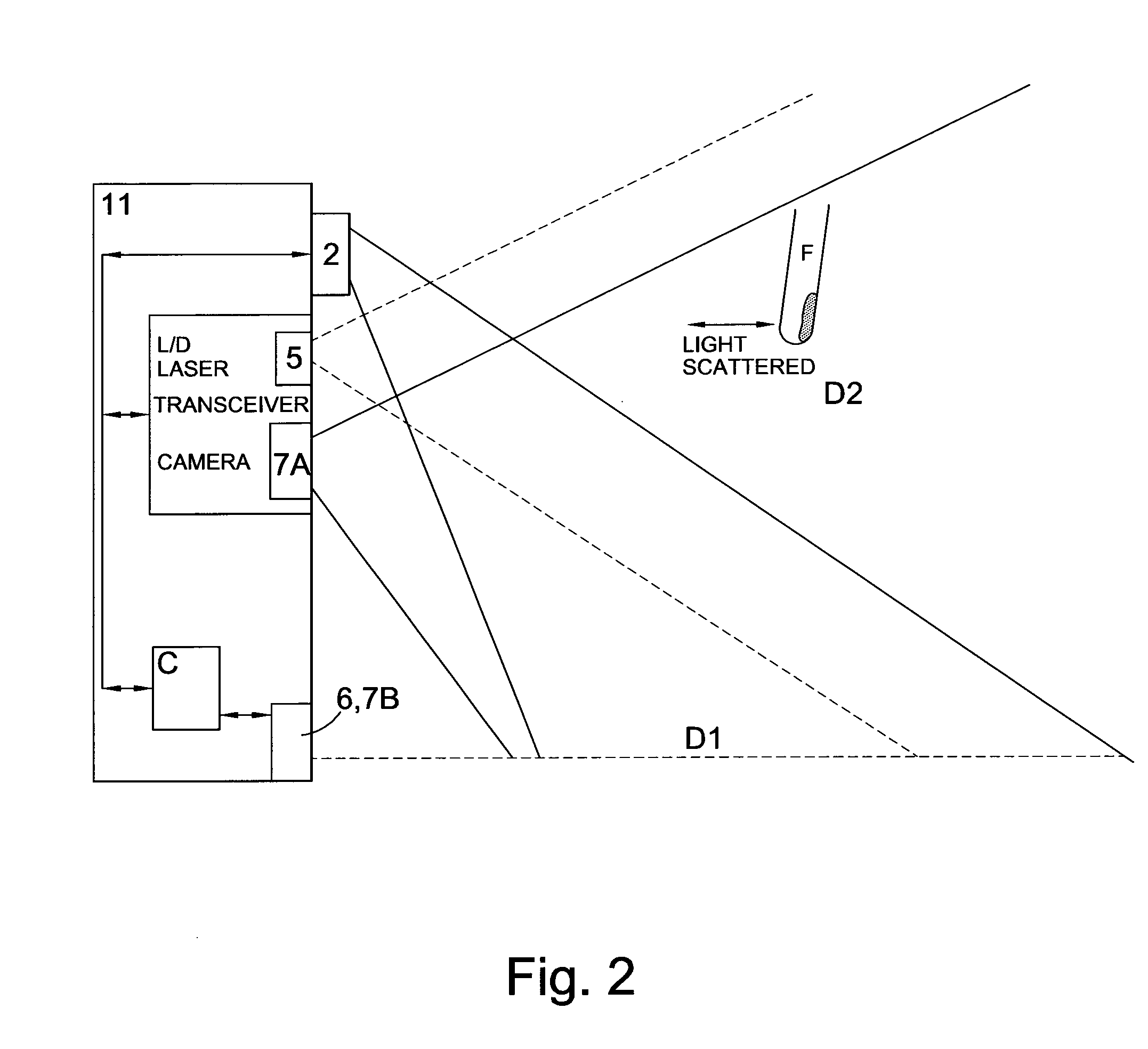
[0089]The following describes an embodiment of a touch sensitive image display device. The embodiment includes a projector for projecting a touch sensitive displayed image at an acute angle onto a surface on which the device is placed. The acute angle is generally less than 90° from the surface where the image is displayed. The angle may be pre-determined or may be adjustable by, for example, moveable optics. The projection optics may comprise a Texas Instruments (registered trademark) digital light processor, a LCOS imager and / or a laser scanner. Furthermore, there may be a projection lens that is moveable or set at a pre-determined angle for projecting the image. Optionally, the image may be projected indirectly to the surface, by first projecting the image to a mirror attached to the housing of the projector, the mirror being arranged to be furth...


PUM


Abstract

We describe a touch sensitive image display device for projecting a touch sensitive displayed image at an acute angle onto a surface on which the device is placed. The device comprises: light sources to project two-dimensional first and second light distributions in respective first and second planes; and a multi-pixel sensor system to remotely detect touch of an area of said surface within or adjacent to the displayed image by detecting light from the first distribution to provide a detected touch signal. The multi-pixel sensor system also remotely detects presence of an object within the second light distribution to provide a detected presence signal. The device is configured to multiplex projection of the first light and second distributions. A controller has an input to receive the detected touch and detected presence signals and is configured to control the device responsive to these signals.

Description

CROSS REFERENCE TO RELATED APPLICATION[0001]This application claims priority to PCT Application No. PCT / GB2009 / 051770 entitled “Display Devices” and filed Dec. 23, 2009, which itself claims priority to Great Britain Patent Application No. GB0823457.7 filed Dec. 24, 2008, claims priority to Great Britain Patent Application No. GB0909313.9 filed May 29, 2009, claims priority to Great Britain Patent Application No. GB0909314.7 filed May 29. 2009. The entirety of each of the aforementioned applications is incorporated herein by reference for all purposes.BACKGROUND OF THE INVENTION[0002]This invention generally relates to a touch sensitive display device and to a consumer electronic device comprising such a device.[0003]We have previously described techniques for displaying an image holographically—see, for example, WO 2005 / 059660 (Noise Suppression Using One Step Phase Retrieval), WO 2006 / 134398 (Hardware for OSPR), WO 2007 / 031797 (Adaptive Noise Cancellation Techniques), WO 2007 / 11066...

Claims


Application Information

Patent Timeline
IPC IPC(8): G06F3/042G06Q50/12
CPCG03H1/0005G06F3/042G03H1/2294G03H2001/0061G03H2001/2215G03H2001/2221G03H2001/2271G03H2210/22G06F1/3231G06F3/0425G06F3/0426G06Q50/12Y02B60/1289G03H2210/441G03H2001/2213G03H1/2205Y02D10/00G03H1/04H04N5/7416
Inventor LAWRENCE, NICHOLAS A.BENET BALLESTER, RAULCABLE, ADRIAN J.WRIGHT, JAMES E. G.
Owner PROMETHEAN
Why Eureka
Try Eureka