Pressure-relief valve of a housing for an electrical/electronic unit

Active Publication Date: 2011-10-13
ROBERT BOSCH GMBH
View PDF7 Cites 22 Cited by
  • Summary
  • Abstract
  • Description
  • Claims
  • Application Information

AI Technical Summary

Benefits of technology

[0003]The object of the invention is to provide a pressure-relief valve of a housing of the generic type that avoids the stated disadvantages and offers sufficient ventilating and venting of the housing, but at the same time avoids the ingress of moisture.
[0007]In one embodiment, the hydrophobic layer is a layer of oil. A layer of oil is a particularly simple and inexpensive form of a hydrophobic layer. In the region of the layer of oil, water is reliably repelled. The layer of oil can possibly be protected from evaporating or be deactivated in a suitable way by the addition of additives.
[0009]In a further embodiment, it is provided that the hydrophobic layer is on both sides of the membrane. In this form, moisture is prevented from passing through particularly reliably. In particular, the use of a water-binding film is also possible here, to be specific on one side or alternatively on both sides of the membrane, the water-binding film expelling water that it has picked up when a specific temperature is reached, in particular an operating temperature of the electrical or electronic unit in the housing, and thereby regenerating itself.

Problems solved by technology

Membranes of this type are already well suited in principle for the application area described, but are not reliably waterproof.

Method used


Image

  • Pressure-relief valve of a housing for an electrical/electronic unit
  • Pressure-relief valve of a housing for an electrical/electronic unit
  • Pressure-relief valve of a housing for an electrical/electronic unit

Examples


Embodiment Construction

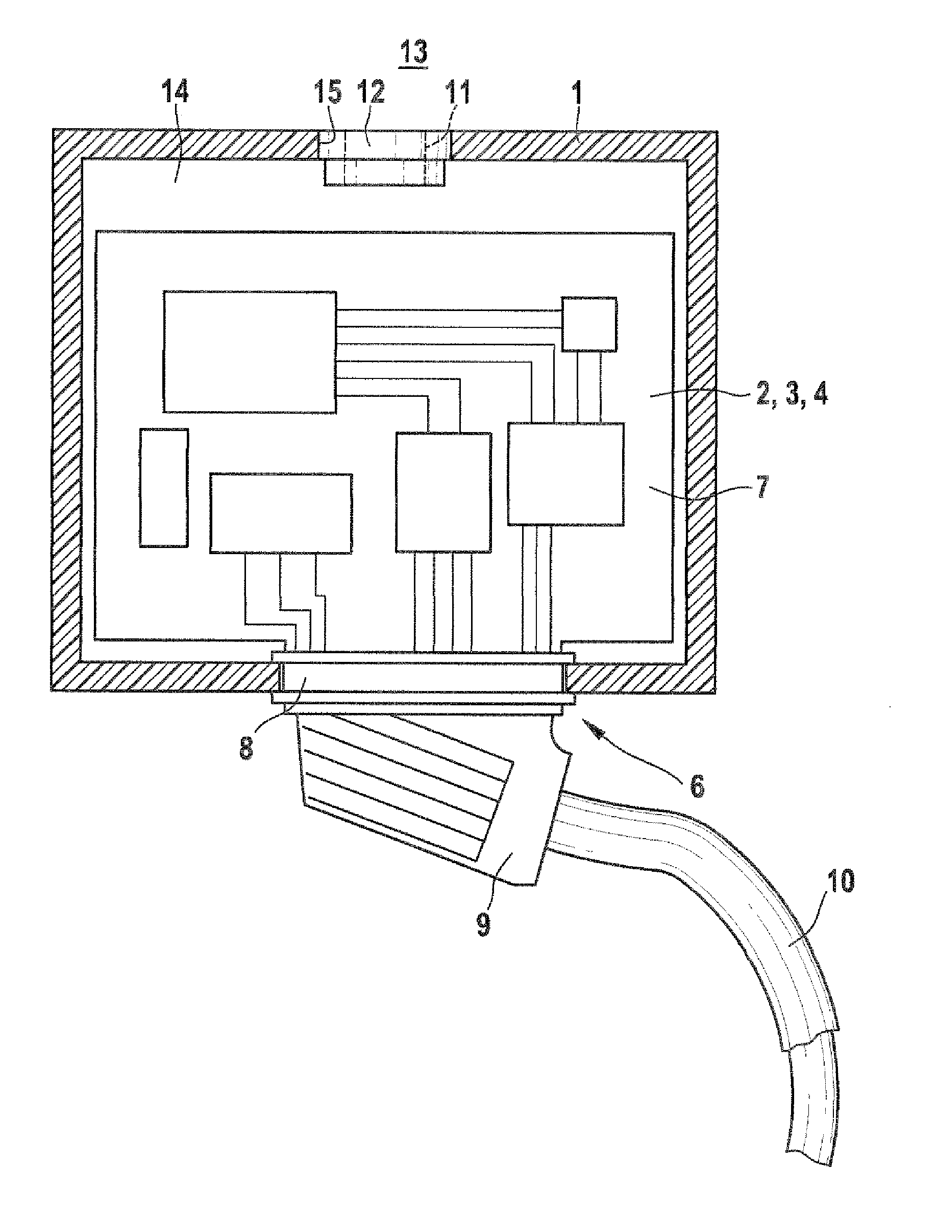
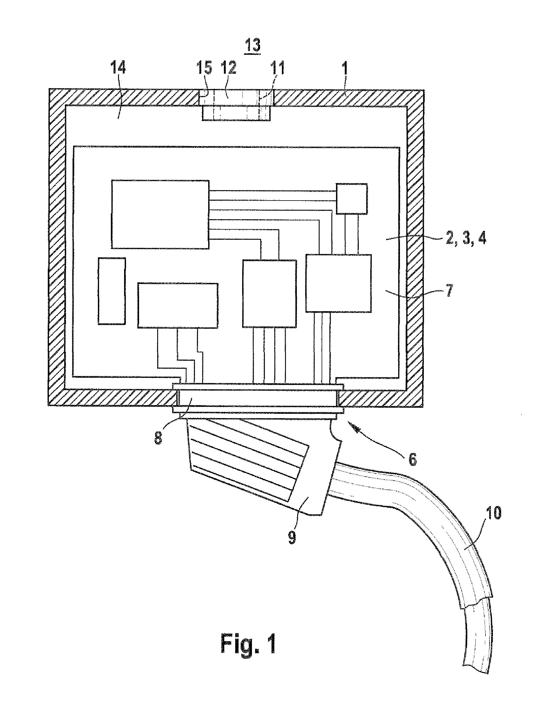
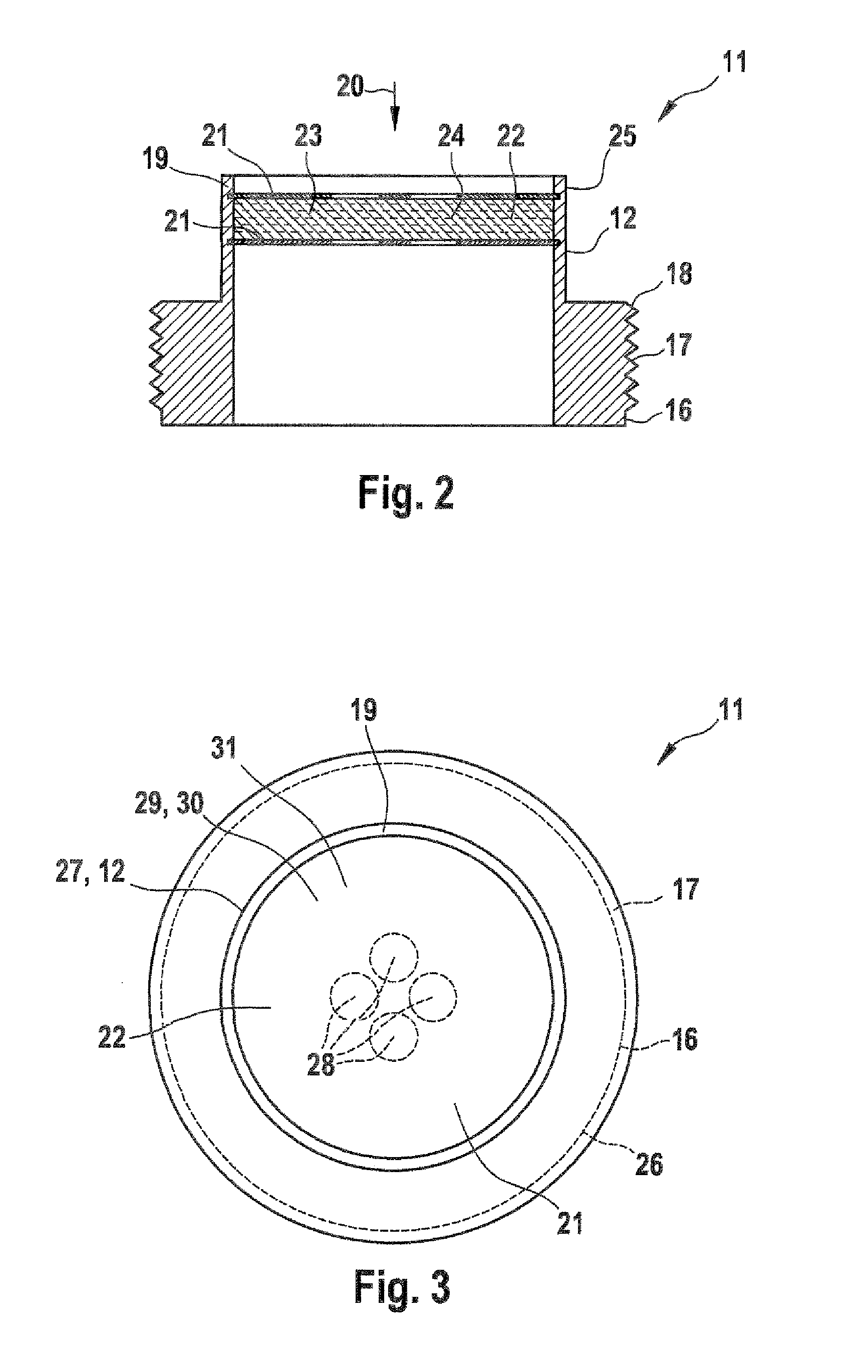
[0017]FIG. 1 shows a housing 1 for an electronic unit 2, to be specific an electronic circuit 3, to be specific a control device 4 for a motor vehicle that is not represented. The housing 1 is accordingly formed as a control device housing 5. The housing 1 has on the underside a connection unit 6, which consists of a male connector 8, which is connected to a printed circuit board 7 of the electronic circuit 3 and is fitted, in particular tightly fitted, in the housing 1, and a female connector9 corresponding thereto, the female connector 9 having a connection cable 10 for connection to further systems that are not represented. The housing 1 is hermetically sealed in the closed state, that is to say for example when the cover is fitted on. To make possible a pressure equalization that is required during the operation of the electronic unit 2, the housing 1 has a pressure-relief valve 11, with a pressure-equalizing element 12, which makes it possible to create a connection between a s...


PUM


Abstract

The invention relates to a pressure-relief valve of a housing for an electrical / electronic unit, particularly for a housing of a control unit of a motor vehicle, comprising a pressure equalization element, which comprises a membrane. It is provided that at least one hydrophobic layer (22) is located on the membrane (21). The invention further relates to a housing (1) for an electrical / electronic unit (2), particularly of a control unit (4) of a motor vehicle, comprising such a pressure-relief valve (11).

Description

BACKGROUND OF THE INVENTION[0001]The invention relates to a pressure-relief valve of a housing for an electrical / electronic unit, with a pressure-equalizing element which comprises a membrane.[0002]Electrical and / or electronic units inserted into housings, in particular control-device circuits of motor vehicles, must be ventilated for necessary pressure equalization, in order to prevent malfunctions from being caused for example by overpressure, underpressure or condensing air moisture. It is known in the prior art to perform such ventilating operations on plug-in elements of a plug / harness connection, which have a passage into the housing at a protected location. A disadvantage of these embodiments is that air moisture or splash water can enter the housing through these passages. In unfavorable cases, this can allow corrosion to occur inside the housing, in particular on the electrical or electronic unit. In other unfavorable cases, such ventilation is inadequate, in particular due...

Claims


Application Information

Patent Timeline
IPC IPC(8): B65D85/00F16K15/00
CPCH05K5/0213Y10T137/3084Y10T137/3003H05K5/0215
Inventor HEBACH, ANDREASKRINGS, NORMAN
Owner ROBERT BOSCH GMBH
Why Eureka
Try Eureka