
Hinge mechanism

a mechanism and hinge technology, applied in the field of hinge mechanisms, can solve the problems of difficult adjustment of pressurization force, no judging method, and inability to confirm the thickness of the wing, and achieve the effect of reducing the noise between the leaf spring and the rotation shaft, and preventing abnormal nois

Inactive Publication Date: 2011-10-06
MITSUBISHI ELECTRIC CORP
View PDF15 Cites 11 Cited by
  • Summary
  • Abstract
  • Description
  • Claims
  • Application Information

AI Technical Summary

Benefits of technology

[0007]The present invention has been made to solve the above-mentioned problems, and an object of the present invention is to provide a hinge mechanism such that when a leaf spring is directly caulked and fixed to a rotation shaft, backlash between the leaf spring and the mounting shaft portion of the rotation shaft is eliminated, to thus suppress abnormal noise that can be generated when the spring force of the leaf spring is released in rotating operation.
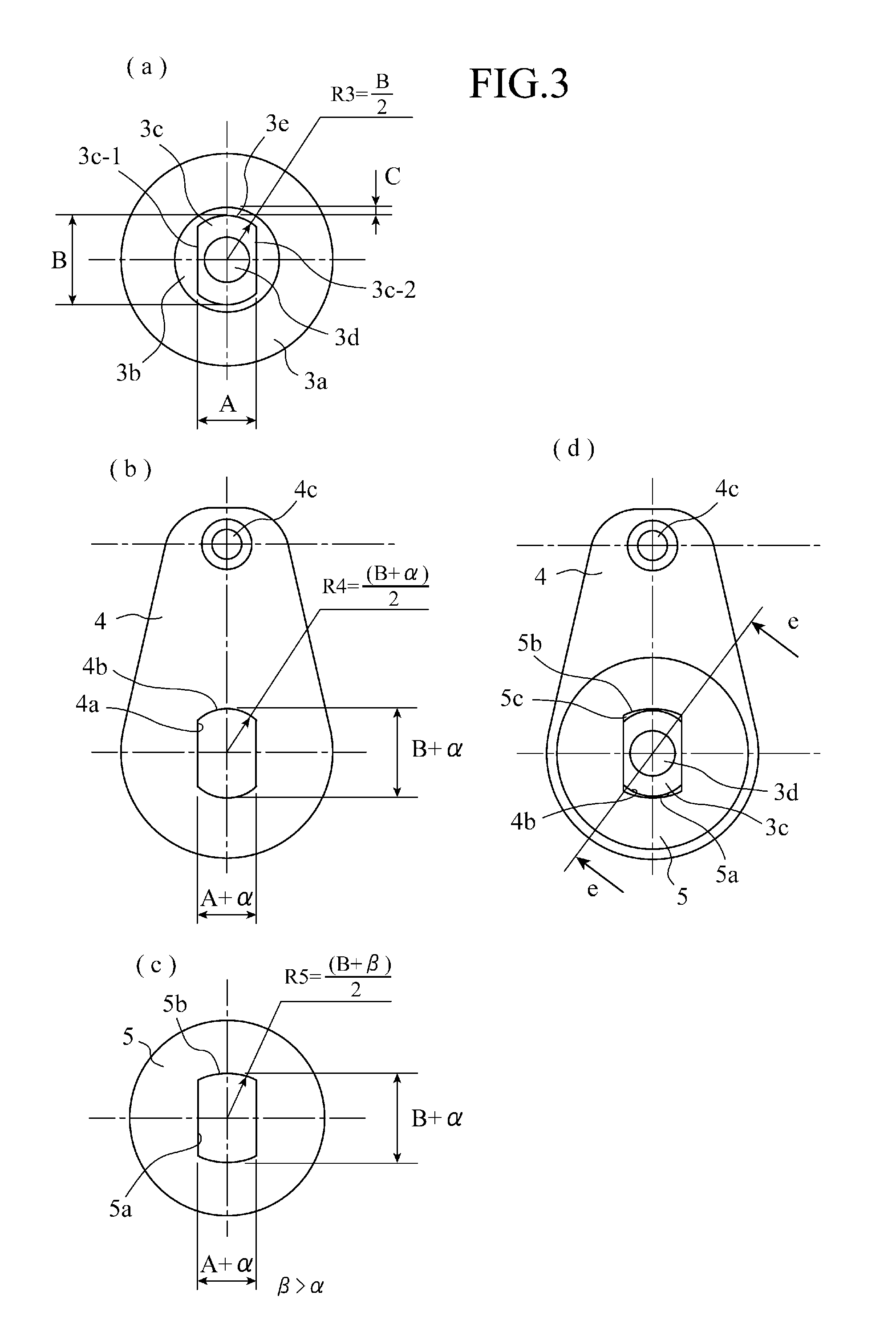
[0009]According to the present invention, the mounting shaft portion insertion hole of the plate is formed larger than the mounting shaft portion insertion hole of the leaf spring, and thus the outer wall side part of the mounting shaft portion that is collapsed by caulking enters the gap formed between the mounting shaft portion insertion hole of the plate and the mounting shaft portion of the rotation shaft to caulk and fix the leaf spring to the end face of the rotation shaft portion. As a result, there is obtained an advantageous effect that the wobble between the leaf spring and the rotation shaft can be eliminated, and abnormal noise can be restrained from being generated when the spring force of the leaf spring is released in rotating operation.

Problems solved by technology

Thus, it is impossible to confirm the entering of the thickness by seeing it from outside, and there is no method of judging whether the portion of the pressing washer has positively entered the peripheral groove of the small diameter portion, in other words, whether the portion thereof has been surely caulked and fixed into the small diameter portion.
Further, since the pressing washer is pressed axially of the rotation shaft with the pressurizing punch, buckling can occur in the medium diameter portion of the rotation shaft, thus making difficult the adjustment of force of pressurization.
Therefore, even when the plate 50 is clamped against the rotation shaft 30 by caulking, there is a dimensional difference between the leaf spring 40 and the non-circular portion 30c of the rotation shaft 30 by the dimension of a fit; thus, there is a problem such that the dimensional difference creates a backlash in an operating section (not shown) of a product using the hinge mechanism, and causes abnormal noise to be generated when the force of the leaf spring is released in rotating operation.

Method used


Image

  • Hinge mechanism
  • Hinge mechanism
  • Hinge mechanism

Examples


first embodiment

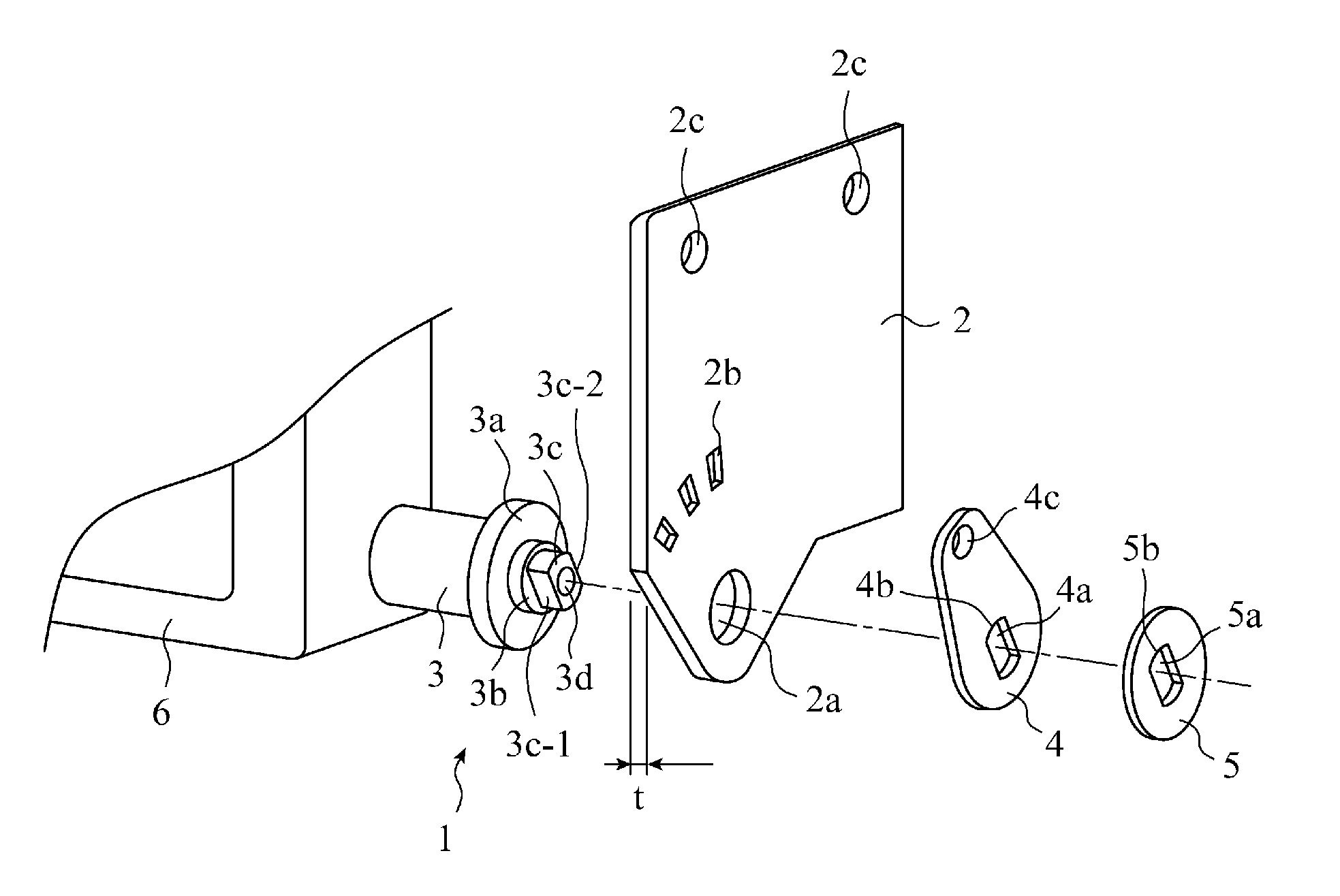
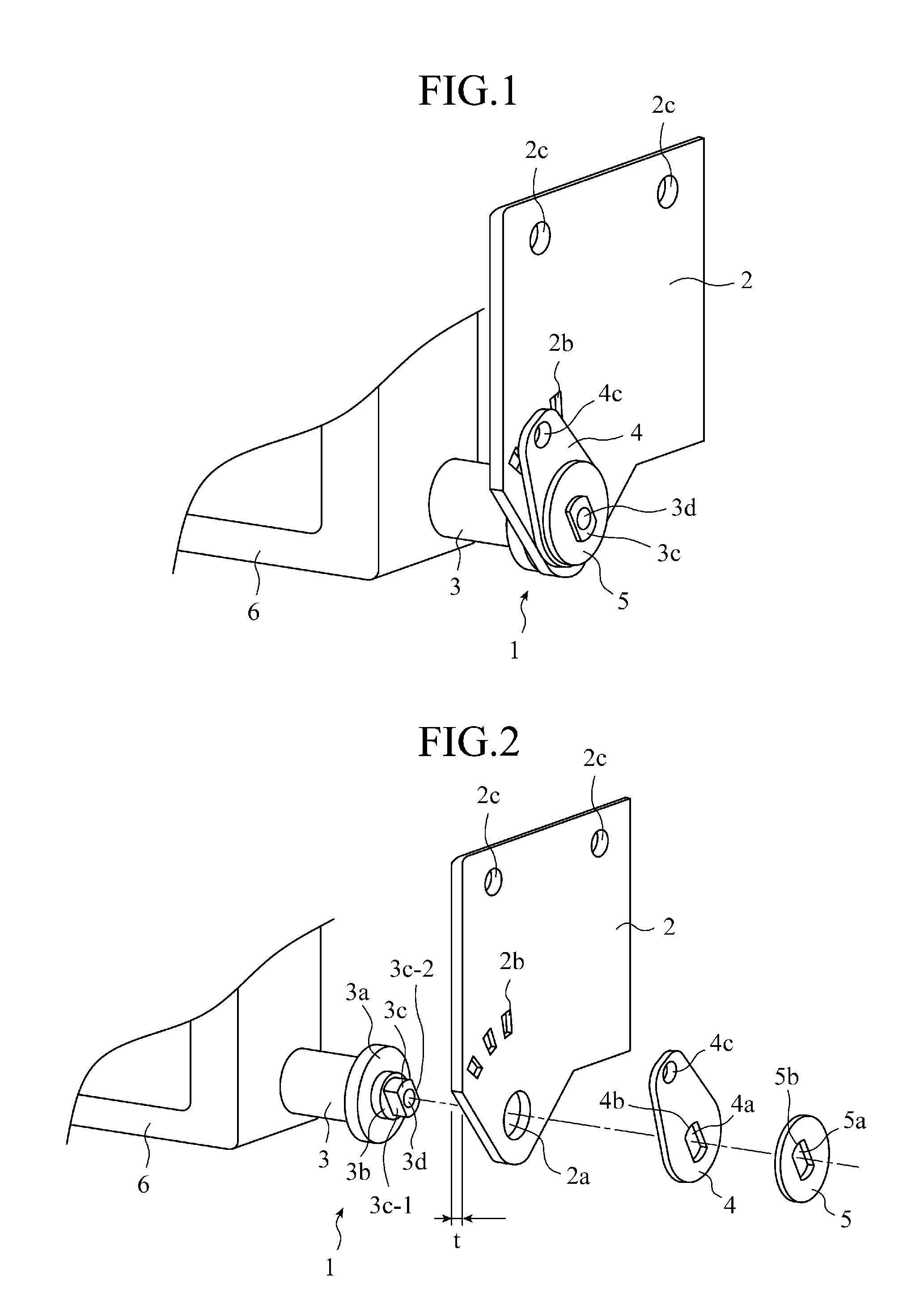
[0019]The present invention will be explained by using as an example a case where a monitor as an openable and closable body is foldably and unfoldably mounted on a housing case (not shown) installed on a ceiling face of a vehicle. As shown in FIG. 1, a hinge mechanism 1 has a structure where a circular portion 3b working as a rotation shaft portion of a rotation shaft 3, which is caused to laterally project from the side of a monitor (openable and closably body) 6, is passed through a circular portion insertion hole (rotation shaft portion insertion hole) 2a of a bracket 2, a leaf spring 4 and a plate 5 are assembled to a non-circular portion 3c serving as a mounting shaft portion provided at the end of the circular portion 3b inserted through the circular portion insertion hole 2a, and the non-circular portion 3c is caulked to rotatably fix the rotation shaft 3 to the bracket 2.

[0020]The constituent members will now be explained in more detail with reference to FIG. 2 and FIG. 3. ...

second embodiment

[0029]A hinge mechanism in accordance with the second embodiment has a structure where the non-circular portion insertion hole 5a of the plate 5 is formed having a generally rectangular shape having a width (A+α) and a height (B+α), and having a small circular arc only at each of four corners as shown in FIG. 5. Therefore, the four corners each have formed therein a gap 5c-1 which is larger than the gap formed in the case shown in FIG. 3(d), and the deformed outer wall side part of the non-circular portion 3c of the rotation shaft 3, which has been collapsed by caulking, fits into the gaps in high amounts, thus enabling a larger caulking effect to be obtained. Moreover, forming the non-circular portion insertion hole 5a thereof so as to have a generally rectangular shape enables a die for forming the non-circular portion insertion hole to be easily built and maintained.

third embodiment

[0030]A hinge mechanism in accordance with the third embodiment has a structure where a sloping face 4d expanded or flared outwardly toward the plate 5 is formed such that a gap 7 is formed between the wall face of the non-circular portion insertion hole of the leaf spring 4 and the plate 5 as shown in FIG. 7. In the case, it is arranged that the non-circular portion insertion hole 4a of the leaf spring 4 and the non-circular portion insertion hole 5a of the plate 5 have the same diameter and shape of hole to each other, and that the non-circular portion insertion hole 4a and the non-circular portion insertion hole 5a have a shape which is slightly larger by the dimension of a fit than that of the non-circular portion 3c of the rotation shaft 3.

[0031]With this arrangement, when the non-circular portion 3c of the rotation shaft 3 is inserted through the non-circular portion insertion hole 4a of the leaf spring 4 and the non-circular portion insertion hole 5a of the plate 5 (FIG. 7 (a...


PUM


Abstract

A hinge mechanism includes: a bracket 2 having a rotation shaft portion insertion hole 2a for inserting through a marginal rotating shaft portion 3b thereof, and one engaging concavo-convex section 2b; a plate 5 having a mounting shaft portion insertion hole 5a; and a leaf spring 4 having a mounting shaft portion insertion hole 4a and the other engaging concavo-convex section 4c, and located between the bracket 2 and plate 5 and mounted to the rotation shaft 3, wherein the hole 5a is formed larger than the hole 4a such that the spring 4 is caulked and fixed to the end face of the shaft portion by entering of the outer wall side part of a mounting shaft portion 3c formed on the end face of the portion 3b that is collapsed by caulking into a gap 5c formed between the portion 3c and insertion hole 5a.

Description

TECHNICAL FIELD[0001]The present invention relates to a hinge mechanism having a click mechanism that holds a monitor at a plurality of angles when the monitor is foldably and unfoldably mounted to a ceiling face of a vehicle, for example.BACKGROUND ART[0002]As this type of hinge mechanism in the prior art, there is a tilt hinge device disclosed in Patent Document 1, for example. The tilt hinge device includes: a mounting member having a base portion and a bearing plate; a rotation shaft at the end thereof having a large diameter portion, a medium diameter portion, and a small diameter portion in this order, and having the medium diameter portion bearing-supported in a bearing hole provided through the bearing plate; a spring washer which is attached to the small diameter portion on the opposite side from the large diameter portion with pinching the bearing plate having the medium diameter portion inserted thereinto; and a pressing washer which is attached to the end of the small di...

Claims


Application Information

Patent Timeline
Patent Type & Authority Applications(United States)
IPC IPC(8): E05F1/12
CPCB60R11/0235B60R2011/0028F16B17/006F16C11/10Y10T16/538Y10T16/557Y10T16/54028Y10T16/553Y10T403/4634
Inventor NAGAMI, TETSURO
Owner MITSUBISHI ELECTRIC CORP
Learn More