
Dental coping and assembly with aligning Anti-rotation feature

a technology of anti-rotation and dental coping, which is applied in the field of dental coping and assembly with anti-rotation feature, can solve the problems that the design may not be sufficient to prevent improper placement of the cap on the component, and achieve the effects of preventing rotation, improving consistency in orienting the cap, and preventing rotational movemen

Inactive Publication Date: 2011-09-22
KEYSTONE DENTAL INC
View PDF20 Cites 14 Cited by
  • Summary
  • Abstract
  • Description
  • Claims
  • Application Information

AI Technical Summary

Benefits of technology

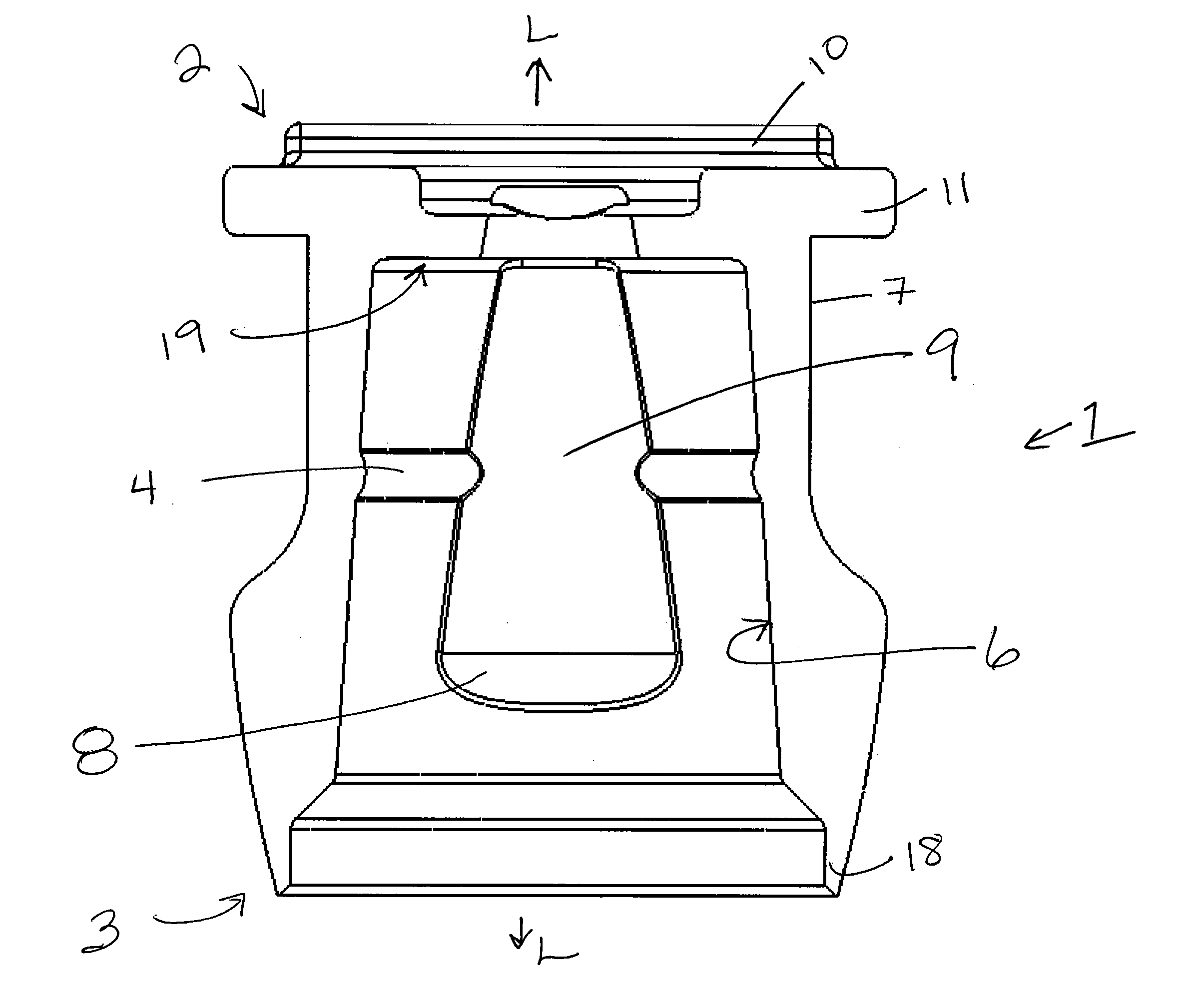
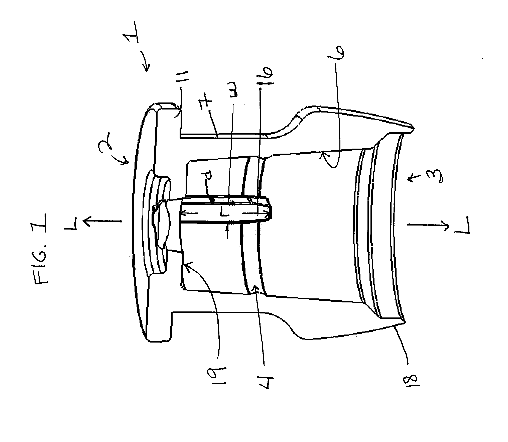
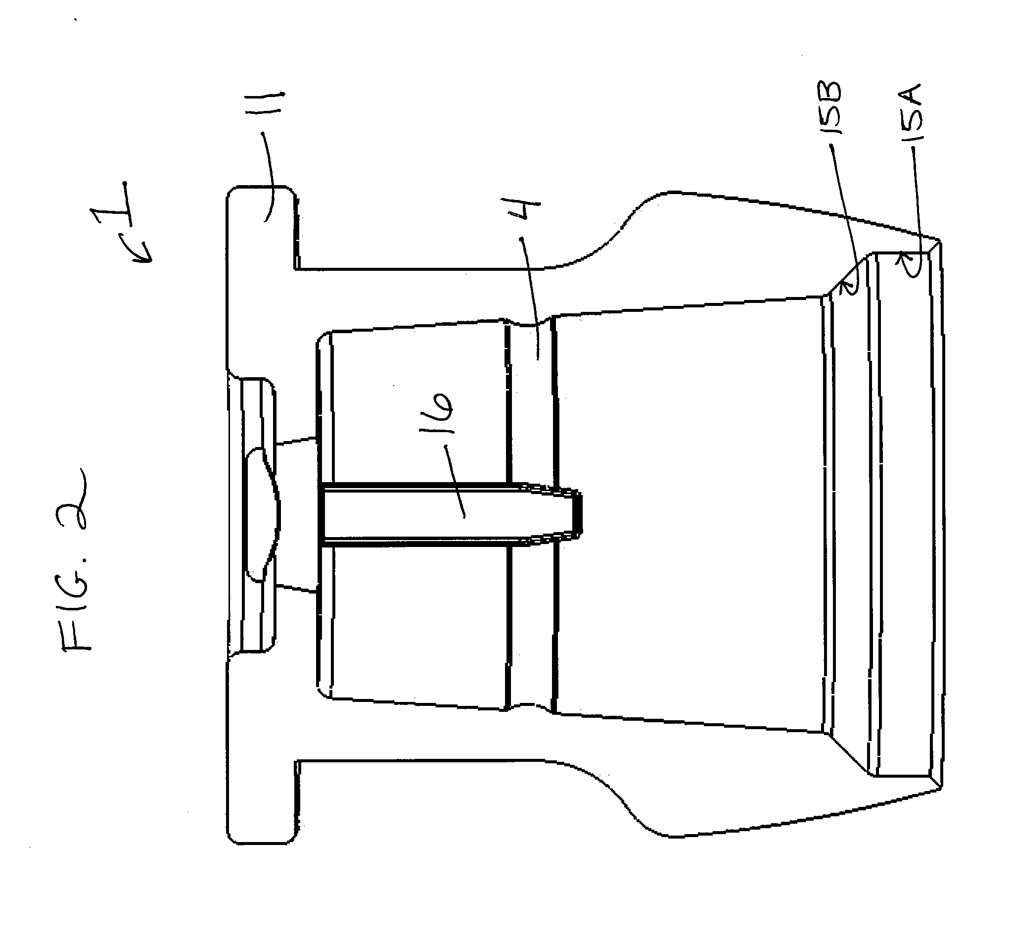
[0005]In view of the foregoing, the present invention relates to an impression cap or other dental coping for removably engaging with a dental component such as an abutment, implant and / or and analog in substantially one orientation. The impression cap or other coping is designed with one or more interior alignment features that provide a precision fit of the cap onto the dental component while substantially preventing rotation between the dental component and the impression cap or other coping. The one or more interior alignment features provide improved consistency in orienting the cap and crown (or other replacement component) on the dental component throughout the impression-making and replacement component fabrication processes and substantially prevent rotational movement between the cap and the dental component. The one or more interior alignment features further may provide a tactile and / or visual indication to the user when the cap and component are not properly aligned.
[0006]More specifically, the present invention relates to an impression cap or other coping including a substantially rigid aligning rib extending from the inner coronal surface and the coronal portion of the inner side surface of the impression cap or other coping that removably engages a groove formed in the corresponding surface of an abutment, implant, analog or other component facilitate consistent and precise orientation and positioning of the coping on the dental component and to prevent substantially rotation between the coping and the component. The aligning rib may be of sufficient length to provide a visual indication that the coping is improperly positioned when the rib is not engaged with the dental component. The aligning rib further may have sufficient rigidity to withstand excessive force when a user is trying to force incorrect mating between the coping and the dental component.
[0007]Optionally, the impression cap or other coping may also include with an interior substantially flat aligning surface positioned substantially opposite to the aligning rib. The flat aligning surface corresponds to a substantially flat surface formed on the exterior surface of the dental component. The impression cap or other coping may also include one or more external alignment features that enable external visual and tactile assistance in aligning the internal alignment surfaces of the cap and the component. The cap may also include one or more chamfered and / or cylindrical surfaces to assist in providing a precision fit of the cap on the component.

Problems solved by technology

However, in practice, this design may not be sufficient to prevent improper placement of the cap on the component or to prevent rotation between the cap and the component.

Method used


Image

  • Dental coping and assembly with aligning Anti-rotation feature
  • Dental coping and assembly with aligning Anti-rotation feature
  • Dental coping and assembly with aligning Anti-rotation feature

Examples


Embodiment Construction

[0022]The present invention will now be described with reference to the accompanying drawings. The accompanying drawings are intended to provide examples of implementations of the present invention, but are not intended to limit the application of the inventive concepts to the illustrated structures. The inventive engagement and alignment features described herein may be implemented in a variety of dental copings, including impression caps, healing caps, burnout copings, and the like, and dental components, such as abutments, implants, analogs, and the like, as would be apparent to one of skill in the art.

[0023]The impression caps and other copings designed in accordance with the present invention are intended to enable alignment between the coping and a dental component in only one specific orientation, or, alternatively, a plurality of specific orientations, each referred to hereinafter as an “aligned orientation.” It is understood that manufacturing tolerances may allow for a ver...


PUM


Abstract

An impression cap or other dental coping is designed to removably engage a dental component such as an abutment, implant and / or and analog in an aligned orientation. The coping includes at least one substantially rigid aligning rib that extends from the inner coronal and side surfaces of the coping and removably engages a groove formed in the corresponding surface of the dental component. The coping may also include a substantially flat aligning surface positioned opposite to the aligning rib in the interior of the coping that contacts a corresponding flat surface on the dental component. The aligning rib and optional flat aligning surface facilitate consistent and precise orientation and positioning of the impression cap or other coping on the dental component, prevent rotation between the coping and component, and also provide a tactile and / or visual indication to the user when the coping and component are not properly aligned.

Description

FIELD OF THE INVENTION[0001]The present invention relates generally to the field of dental components, and more specifically to components used during the process of taking an impression of a patient's mouth to record accurately the position and orientation of an implant site to enable accurate fabrication of restorative components. The inventive components include an impression cap or other coping for use in a pick-up impressioning method and abutments, implants, analogs and other dental components that are designed to removably engage the impression cap.BACKGROUND OF THE INVENTION[0002]Dental implants are widely used to replace lost or damaged natural teeth. The insertion of an implant may be accomplished in several stages. First, an implant is positioned in the maxillary or mandibular bone of the patient and allowed to heal for a period of time, during which osseointegration of the implant into the bone occurs. A healing cap may be positioned over the implant during this time. Af...

Claims


Application Information

Patent Timeline
IPC IPC(8): A61C13/225
CPCA61C8/0001
Inventor BRETTON, JOSEPH N.NICOLAISEN, ANDREADE ANGELO, JOHN T.
Owner KEYSTONE DENTAL INC
Learn More