
Safety central shaft extension and contraction control structure of self-opening/closing umbrella

Inactive Publication Date: 2011-09-22
LO TZU CHIEN
View PDF6 Cites 11 Cited by
  • Summary
  • Abstract
  • Description
  • Claims
  • Application Information

AI Technical Summary

Benefits of technology

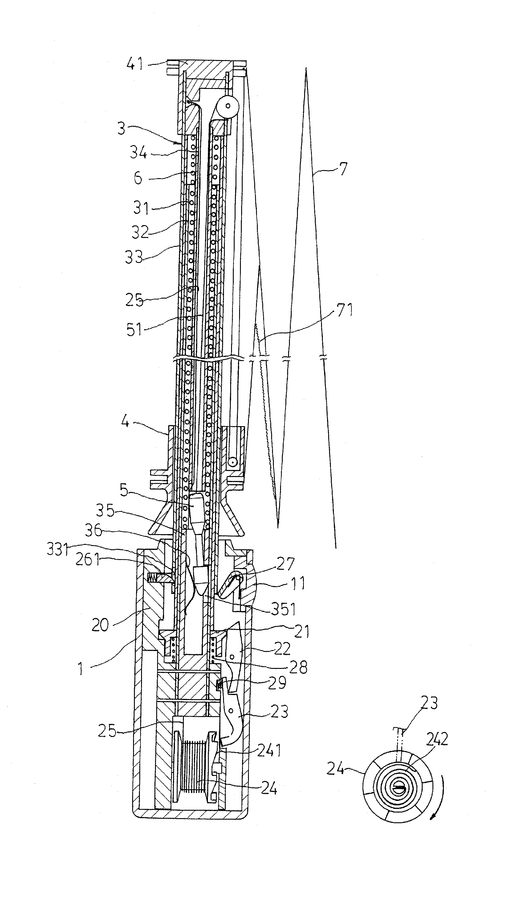
[0006]The present invention provides a safety control structure for controlling extension and contraction of a central shaft of a collapsible umbrella in a safe manner and the control structure according the present invention is generally designated at 2 as shown in FIG. 4. The control structure 2 of the present invention comprises the following constituent components including a main body 20, a collar 21, an operation plate 22, a pawl plate 23, and a reversal prevention wheel 24. A lining tube 35 that forms an opening 351 in a side thereof is received and fixed in a lower end of a first shaft segment 31 of a central shaft unit 3 of the umbrella, which will be further described and is received and fixed inside the main body 20. The first shaft segment 31 also forms a hole 311 in a side thereof close to the lower end and also forms an elongate groove 312, in which an opening 313 is formed at an upper end thereof, in an adjacent side of the first shaft segment 31. The collar 21 receives therein a spring 28 that is fit over the first shaft segment 31. The operation plate 22 and the pawl plate 23 are set in engagement with each other and are mounted to the main body 20 to be located below one side of the collar 21. The pawl plate 23 is biased at one side thereof by a spring 29. The reversal prevention wheel 24 is mounted to the main body 20 and located below the pawl plate 23 and has one side forming a toothed surface 241 that forms thereon a plurality of ratchet teeth that are inclined in the same direction. The reversal prevention wheel 24 receives therein a coil spring 242. A safety rope 25 is wrapped around the reversal prevention wheel 24 and has an end fixed to the reversal prevention wheel 24 and an opposite end extending along the elongate groove 312 of the first shaft segment 31 and extending through the opening 313 into the interior space of the central shaft unit 3 to attach upward to a crown 41 of the umbrella. During the closing of the umbrella, when the operation of compressing the central shaft of the umbrella is in error, with the engagement that is instantaneously formed between the pawl plate 23 and the reversal prevention wheel 24 and the pulling action provided by the safety rope 25, the central shaft unit 3 that is in the process of being compressed is kept in position thereby preventing abrupt extension of the central shaft unit 3 caused by the action of an umbrella opening spring 6. By using this kind of arrangement of safety that directly works on the central shaft of an umbrella, absolute safety for the use and control of umbrella opening can be ensured.

Problems solved by technology

However, a problem of the above mentioned self-opening / closing umbrella occurs in the course of compressing and closing of the umbrella.
This often hurts the hands or other portions of the body of the user.
Thus, the closing operation of the known self-opening / closing umbrella is dangerous and improvement in this respect is needed.

Method used


Image

  • Safety central shaft extension and contraction control structure of self-opening/closing umbrella
  • Safety central shaft extension and contraction control structure of self-opening/closing umbrella
  • Safety central shaft extension and contraction control structure of self-opening/closing umbrella

Examples


Embodiment Construction

[0013]The following descriptions are exemplary embodiments only, and are not intended to limit the scope, applicability or configuration of the invention in any way. Rather, the following description provides a convenient illustration for implementing exemplary embodiments of the invention. Various changes to the described embodiments may be made in the function and arrangement of the elements described without departing from the scope of the invention as set forth in the appended claims.

[0014]The present invention provides a safety control structure for controlling extension and contraction of a central shaft of a collapsible umbrella in a safe manner and the control structure according the present invention is generally designated at 2 as shown in FIG. 4. The control structure 2 of the present invention comprises the following constituent components including a main body 20, a collar 21, an operation plate 22, a pawl plate 23, and a reversal prevention wheel 24. A lining tube 35 t...


PUM


Abstract

A safety central shaft extension and contraction control structure is mounted in a handle of a self-opening / closing umbrella and includes a main body mounted to a first shaft segment of the central shaft. Mounted to a lower portion of the main body are an operation plate and a pawl plate, which are in engagement with each other, and a reversal prevention wheel having a toothed surface. A safety rope is wrapped around the reversal prevention wheel and has an end attached to a crown of the umbrella. When errors occur in the course of compression of the central shaft in closing the umbrella, the central shaft that is being compressed can be held in position, so that instantaneous spring back of the central shaft caused by an umbrella opening spring that is in a compressed condition can be prevented to ensure safety of operation and control of the self-opening / closing umbrella.

Description

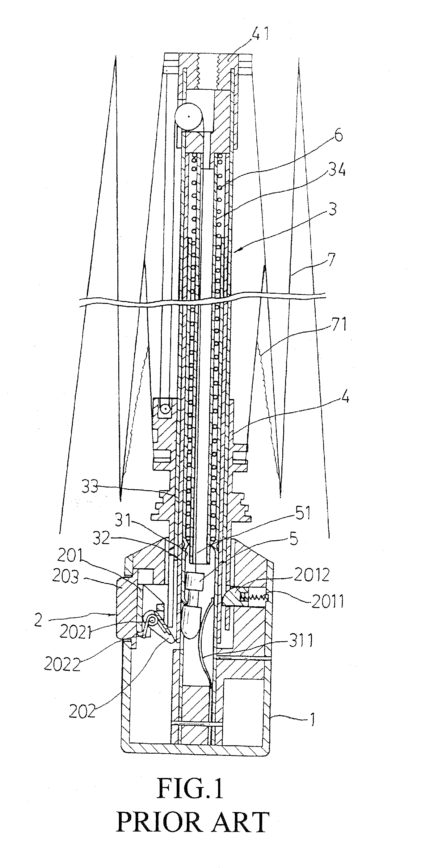
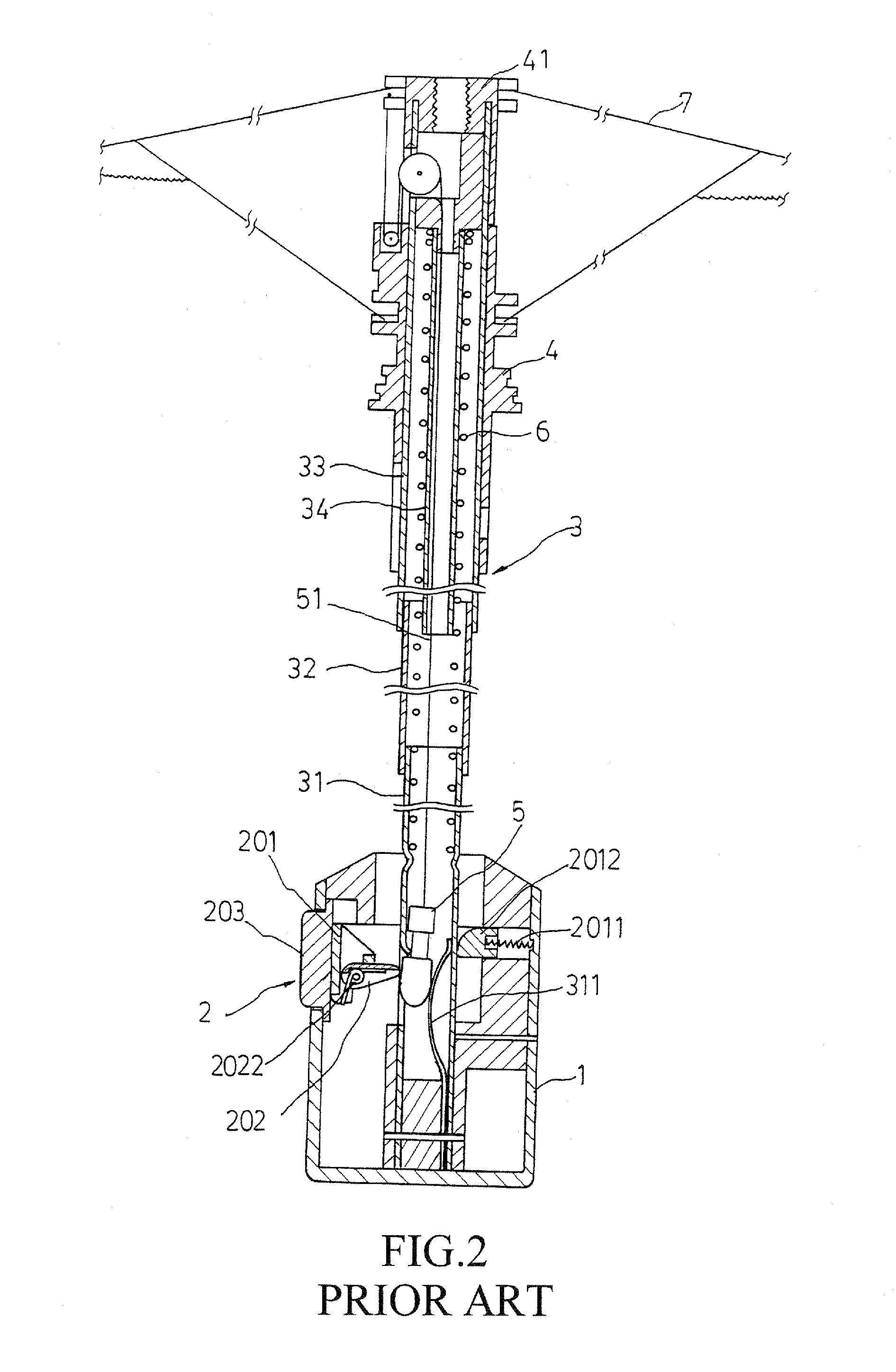
(a) TECHNICAL FIELD OF THE INVENTION[0001]The present invention generally relates to a self-opening / closing umbrella, and more particularly to a centrals shaft control structure of a self-opening / closing umbrella.(b) DESCRIPTION OF THE PRIOR ART[0002]A conventional self-opening / closing umbrella is shown in FIGS. 1-3. The known umbrella comprises a handle 1 inside which an operation unit 2 is provided, a central shaft unit 3 inside which an umbrella opening spring 6 is received, and a runner 4 coupled to ribs 7 and comprising a pull rope 51 wrapping therearound and having an end fixed to a crown 41 and an opposite end fixed to a bullet-head member 5. The operation unit 2 comprises a hollow body inside which components including a control ring 201, a control bar 202, and a pushbutton 203 are received. The control bar 202 is pivoted to a lower portion of one side of the bottom of the control ring 201. The pushbutton 203 is received in an opening formed in a side wall of the handle 1 an...

Claims


Application Information

Patent Timeline
IPC IPC(8): A45B25/14
CPCA45B25/16A45B25/14
Inventor LO, TZU-CHIEN
Owner LO TZU CHIEN
Learn More