Low-oxygen-region-analysis method and apparatus by time-resolved-measurement of light-induced-autofluorescence from biological-sample

a technology of low-oxygen region and light-induced fluorescence, which is applied in the field of low-oxygenregion analysis methods and apparatuses by time-resolved measurement of light-induced fluorescence from biological samples, can solve the problems of insufficient reliability of methods, difficult to achieve excellent quantitative detection and high-sensitivity detection, and damage to the target of measuremen

Inactive Publication Date: 2011-09-15
FUJIFILM CORP +1
View PDF7 Cites 6 Cited by
  • Summary
  • Abstract
  • Description
  • Claims
  • Application Information

AI Technical Summary

Benefits of technology

The advantageous effects of the oxygen concentration measurement apparatus 1, as described above, are achievable also by oxygen concentration measurement apparatuses in other embodiments that will be described later.
“Second Embodiment of Oxygen Concentration Measurement Apparatus (Fiber Probe)”
Next, an oxygen concentration measurement apparatus according to another embodiment of the present invention will be described. The oxygen concentration measurement apparatus 1 in the first embodiment is a microscope. However, an oxygen concentration measurement apparatus 10 in the second embodiment is a fiber probe. In the descriptions of the present embodiment and the drawings, the same signs will be assigned to elements that have substantially the same functions as those of the first embodiment, and explanations will be omitted.
As illustrated in FIG. 7, the structure of the oxygen concentration measurement apparatus 10 is similar to the structure of Embodiment 1, except that the objective lens 21 (31) in the first embodiment is replaced by a bundle fiber 21′ (31′) in the second embodiment.
In the bundle fiber 21′ (31′), an optical fiber 200 for illumination is arranged substantially at the center. The optical fiber 200 for illumination guides the pulsed excitation L1 toward a central part, and illuminates a predetermined position in the substance D to be measured with the excitation light L1. Further, plural optical fibers 300 for receiving light are arranged so as to surround the outer surface of the optical fiber 200 for illumination. The optical fibers 300 for receiving light receive light L3 including fluorescence Lf emitted, by illumination with the excitation light L1, from autofluorescent material P contained in the substance D to be measured, the fluorescence lifetime of the autofluorescent material P being longer than or equal to 1 nanosecond. Further, the optical fibers 300 for receiving light guide the light L3 to the time-resolving means 40. In FIG. 7, seven optical fibers 300 for receiving light are illustrated. However, it is not necessary that the number of the optical fibers 300 for receiving light is seven. At least one optical fiber for illumination and at least one optical fiber for receiving light should be provided, and the number of fibers and the fiber diameters may be appropriately selected based on receivable fluorescence intensity or the like. An objective lens is attached to the leading end of the optical fiber for illumination.
The low oxygen region detection apparatus 2 (2′) of the present embodiment includes the oxygen concentration measurement apparatus of the above embodiment. Therefore, the low oxygen region detection apparatus 2 (2′) can achieve an advantageous effect similar to the oxygen concentration measurement apparatus 1 (1′).

Problems solved by technology

Therefore, in the method disclosed in Patent Document 1, excellent quantitative detection and high sensitivity detection are difficult, and the method is not sufficiently reliable.
Further, in the method disclosed in Patent document 2, since the probe is directly administered, there is a risk of greatly damaging the target of measurement.
Hence, there is a problem that quick measurement is not possible.

Method used


Image

  • Low-oxygen-region-analysis method and apparatus by time-resolved-measurement of light-induced-autofluorescence from biological-sample
  • Low-oxygen-region-analysis method and apparatus by time-resolved-measurement of light-induced-autofluorescence from biological-sample
  • Low-oxygen-region-analysis method and apparatus by time-resolved-measurement of light-induced-autofluorescence from biological-sample

Examples


first embodiment

of Oxygen Concentration Measurement Apparatus (Measurement Apparatus) (Microscope)

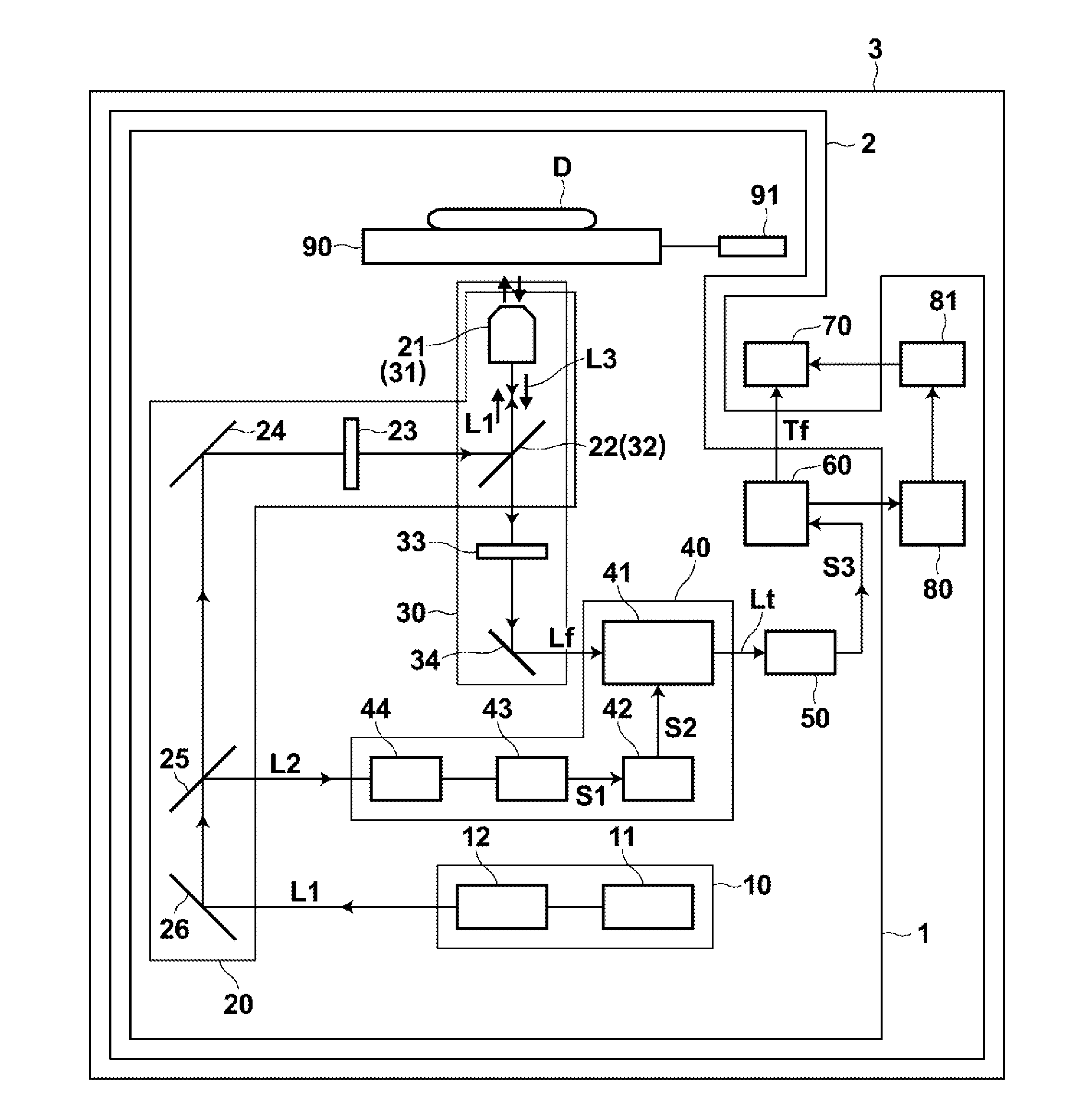
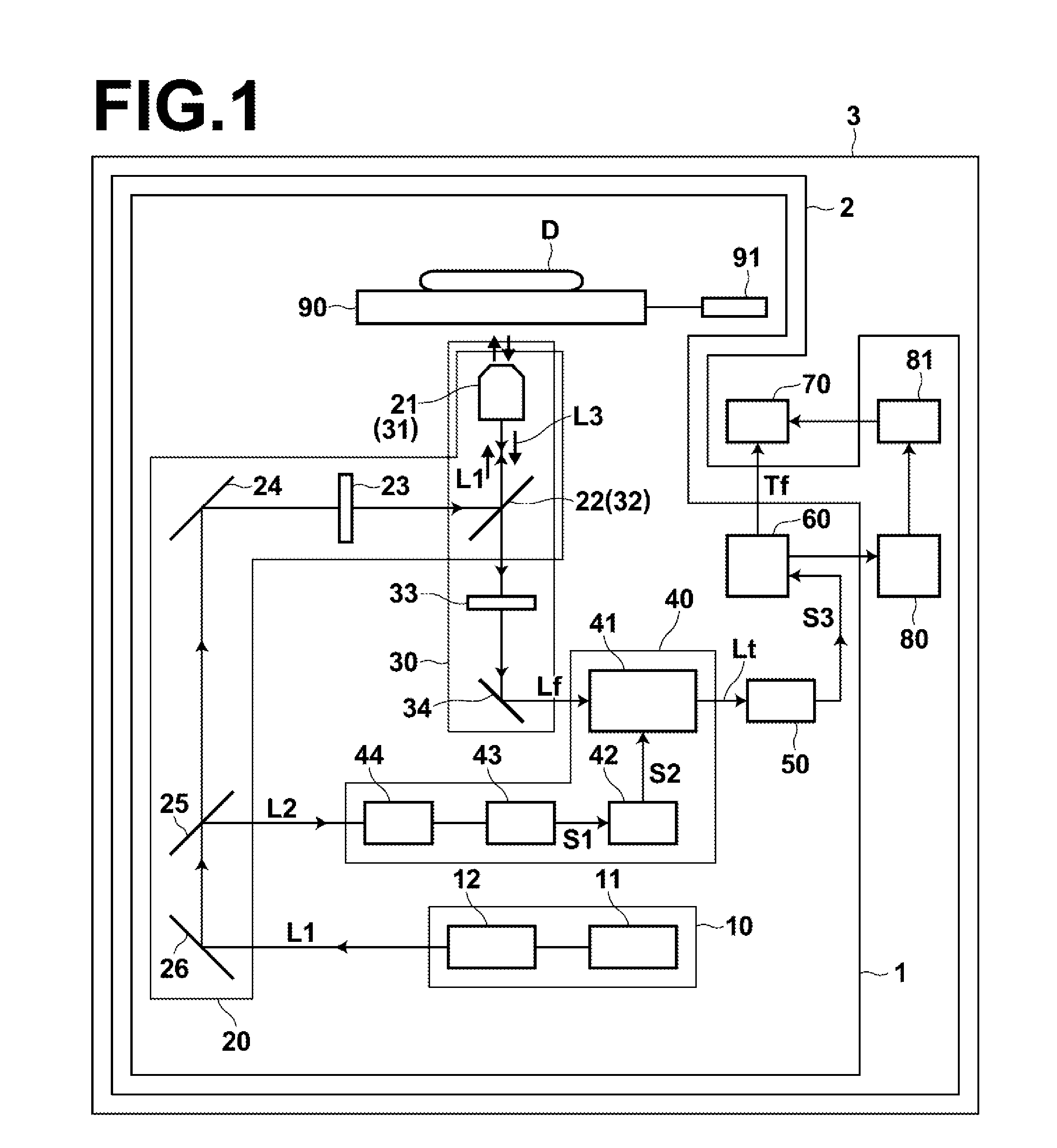
An oxygen concentration measurement apparatus and an oxygen concentration measurement method according to a first embodiment of the present invention will be described with reference to drawings. FIG. 1 is a schematic diagram illustrating the configuration of an oxygen concentration measurement apparatus 1 according to an embodiment of the present invention. In FIG. 1, each unit is illustrated at an appropriate scale so as to be easily recognized.

As illustrated in FIG. 1, the oxygen concentration measurement apparatus 1 outputs pulsed excitation light L1 (hereinafter, referred to as excitation light L1) to substance D to be measured, which is living matter, by an excitation light illumination means 20. Further, the oxygen concentration measurement apparatus 1 obtains fluorescence by receiving light L3 by a light receiving means 30. The light L3 includes fluorescence Lf emitted, by illumination with the...

second embodiment

“Second Embodiment of Oxygen Concentration Measurement Apparatus (Fiber Probe)”

Next, an oxygen concentration measurement apparatus according to another embodiment of the present invention will be described. The oxygen concentration measurement apparatus 1 in the first embodiment is a microscope. However, an oxygen concentration measurement apparatus 10 in the second embodiment is a fiber probe. In the descriptions of the present embodiment and the drawings, the same signs will be assigned to elements that have substantially the same functions as those of the first embodiment, and explanations will be omitted.

As illustrated in FIG. 7, the structure of the oxygen concentration measurement apparatus 10 is similar to the structure of Embodiment 1, except that the objective lens 21 (31) in the first embodiment is replaced by a bundle fiber 21′ (31′) in the second embodiment.

In the bundle fiber 21′ (31′), an optical fiber 200 for illumination is arranged substantially at the center. The o...

example 1

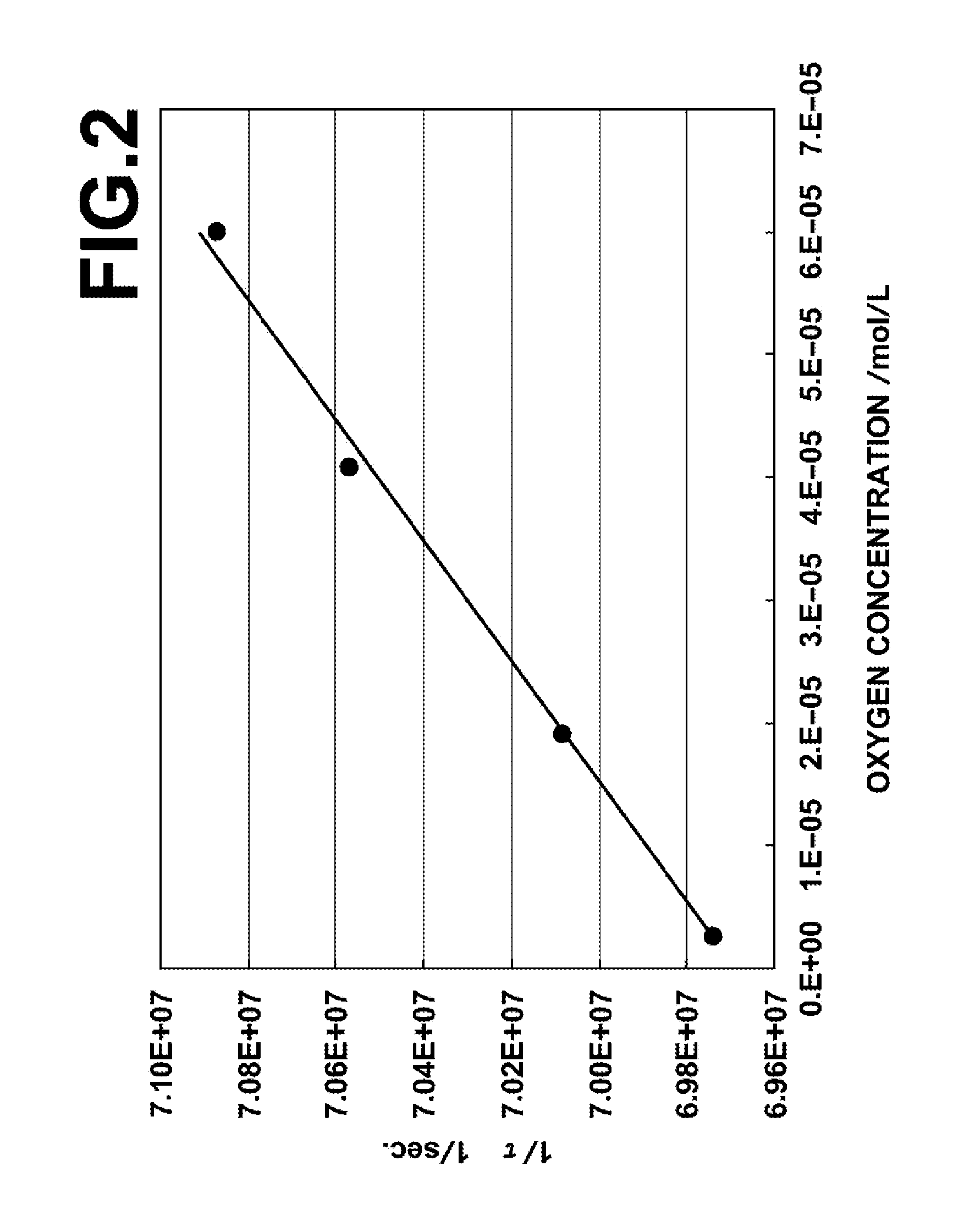
Oxygen concentration of a cultured HeLa cell was measured by using a microscope-type oxygen concentration measurement apparatus illustrated in FIG. 1. FAD (Flavin Adenine Dinucleotide) was used as an autofluorescent material to be excited, and SHG light of a titanium sapphire laser with a pulse width of 1 picosecond was used as excitation light. Further, the wavelength of the excitation light was adjusted so that the wavelength became 450 nm, which is the excitation wavelength of FAD. At this time, the pulse energy of excitation light was 25 nJ.

The pH of HeLa cells was adjusted to pH 7.4 in culture medium, and two kinds of HeLa cell with oxygen concentration of 5 mmHg and oxygen concentration of 40 mmHg were prepared. Further, fluorescence lifetimes of the two kinds of HeLa cell were measured for fluorescence wavelength of 520 nm. In living matter, FAD is present in a protein bond state and in a free state. However, FAD in the free state the fluorescence lifetime of which was longer...


PUM


Abstract

Pulsed excitation light including a wavelength that can excite a fluorescent material contained in living matter is generated. The fluorescence lifetime of the fluorescent material is longer than or equal to 4.8 nanoseconds. A predetermined position in the living matter is illuminated with the pulsed excitation light. Further, light including fluorescence emitted from the fluorescent material excited by illumination with the pulsed excitation light is received. The lifetime of the fluorescence included in the received light is calculated by time-resolving the intensity of the fluorescence. Further, the oxygen concentration of the living matter is measured based on the lifetime.

Description

BACKGROUND OF THE INVENTION1. Field of the InventionThe present invention relates to a method for measuring the concentration of oxygen of living matter, a method for detecting a low oxygen concentration region based on the concentration of oxygen, a method for analyzing the living matter based on the result of measurement and the result of detection, and apparatuses for carrying out these methods.2. Description of the Related ArtAs a method for distinguishing normal tissue and abnormal tissue of living matter from each other, various methods have been tried. In the methods, the oxygen concentration of the living matter is measured based on a difference in the physical properties of a substance that is used as a label, and the normal tissue and the abnormal tissue are identified based on the difference in oxygen concentration.For example, there is a method in which a fluorescent material that is present in living matter is used as a label, and a difference in the intensity of fluore...

Claims


Application Information

Patent Timeline
Patent Type & Authority Applications(United States)
IPC IPC(8): A61B5/00
CPCA61B5/0071G01N33/84G01N21/6486G01N21/6408A61B5/0068
Inventor ADACHI, TAKASHIOGIKUBO, SHINYAOHTA, NOBUHIRONAKABAYASHI, TAKAKAZU
Owner FUJIFILM CORP
Why Eureka
Try Eureka