Leaf spring attachment

a technology of leaf springs and bolts, which is applied in the direction of resilient suspensions, vehicle springs, pivoted suspension arms, etc., can solve the problems of unwanted weakening of the cross section the relative length of the screw bolt or the tensioning clamp, and the general pressure on the surface of the leaf spring, so as to improve the positioning of the elastomer body, easy assembly and disassembly, and easy replacement during repair. , the effect o

Active Publication Date: 2011-09-15
BENTELER AUTOMOBILTECHNIK GMBH
View PDF8 Cites 12 Cited by
  • Summary
  • Abstract
  • Description
  • Claims
  • Application Information

AI Technical Summary

Benefits of technology

[0014]Regardless of the type of joining technique, it is possible to configure the elastomer body itself as composite material. It is even conceivable to integrate at least one metal inlay in the elastomer body. The presence of a metal inlay and the selection of a Shore hardness of a elastomeric base material renders it possible to influence the resultant pretension force profile in order to adjust the targeted surface pressure in the desired manner.
[0015]Although it would be conceivable to bond the at least one elastomer body on its leaf spring distal side with the axle or frame of the vehicle and leaf spring clamp, respectively, this makes it more difficult to replace during repair. Therefore, it is currently preferred to provide a form-fitting engagement of the leaf spring distal side of the at least one elastomer body with the clamp. In this way, one side of the elastomer body has a connection by material joint and the other side of the elastomer body has a connection by form-fitting engagement which ensures that the leaf spring is fixed in place in relation to the clamp, on one hand, and permits easy assembly and disassembly, on the other hand.
[0016]According to another advantageous feature of the present invention, an inlay may be disposed in a region for integration in the at least one elastomer body, with the inlay disposed in a region which is in form-fitting engagement with the clamp. The inlay may be made of metal. The inlay may be connected with an elastomer body of rubber through vulcanization and may be placed in a groove of the clamp so that the elastomer body can assume only one position in relation to the groove. The presence of a inlay, especially of metal, provides improved positioning of the elastomer body in relation to the groove compared to an elastomer body without inlay in view of the softer material of the elastomer body.
[0017]According to another advantageous feature of the present invention, the retention plates define a gap which can be configured to be suitable for a form-fitting engagement with the at least one elastomer body. To prevent the elastomer body from rubbing against the gap and thus to prevent damage, the retention plates can have angled flanges so that the gap receives a wedge-shaped configuration. The wedge shape results in a reliable centering, on one hand, and by providing a radiused transition zone to the angled flanges contact surfaces to the elastomer body are created which are gentle to the material and do not cut.
[0018]According to another advantageous feature of the present invention, the retention plates may have a generally U-shaped configuration defining flanges which face away from the leaf spring and are directed towards the axle and connected to the axle by material joint. The flanges can thus be made of varying lengths. Also, there is no need for the flanges to extend in parallel relationship. An essential feature is only a support of both flanges of the lower retention plate directly upon the axle so as to realize a direct force introduction over a short path. There is no need for further screwed connections so that the overall arrangement becomes lightweight and compact.
[0019]According to another advantageous feature of the present invention, the upper clamp member may have an H-shaped configuration defined by two spaced-apart parallel legs which span a width of the leaf spring, and by a bridge which interconnects the parallel legs and is dimensioned to extend in length direction of the leaf spring. The H-shaped configuration provides a defined spacing between the parallel legs relative to one another. At the same time, the screw connection in the region of the parallel legs for attachment with the lower clamp member substantially results in a tension force which is applied on the elastomer body and thus on the leaf spring via the parallel legs. The space between the parallel legs and the bridge is indirectly urged via the parallel legs against the elastomer body and thus against the leaf spring. Therefore, the parallel legs should thus be made as solidly as possible to apply the necessary surface pressure whereas the bridge may be configured lightweight. Advantageously, the bridge can be configured of U-shaped cross section and open towards the leaf spring.

Problems solved by technology

Conventional leaf springs are subject to great surface pressure because the screwed connections that connect the leaf spring to the axle or the frame of the vehicle become loose as the system settles and thus must be compensated.
Another drawback is the relative long length of screw bolts or tensioning clamps because of their additional use to press the clamp assembly against the leaf spring.
Proposals to drill holes in the leaf spring in order to fix the position of the leaf spring relative to the clamp assembly also suffer shortcomings because this approach leads to an unwanted weakening in the cross section of the leaf spring.

Method used


Image

  • Leaf spring attachment
  • Leaf spring attachment
  • Leaf spring attachment

Examples


Embodiment Construction

[0026]Throughout all the figures, same or corresponding elements may generally be indicated by same reference numerals. These depicted embodiments are to be understood as illustrative of the invention and not as limiting in any way. It should also be understood that the figures are not necessarily to scale and that the embodiments are sometimes illustrated by graphic symbols, phantom lines, diagrammatic representations and fragmentary views. In certain instances, details which are not necessary for an understanding of the present invention or which render other details difficult to perceive may have been omitted.

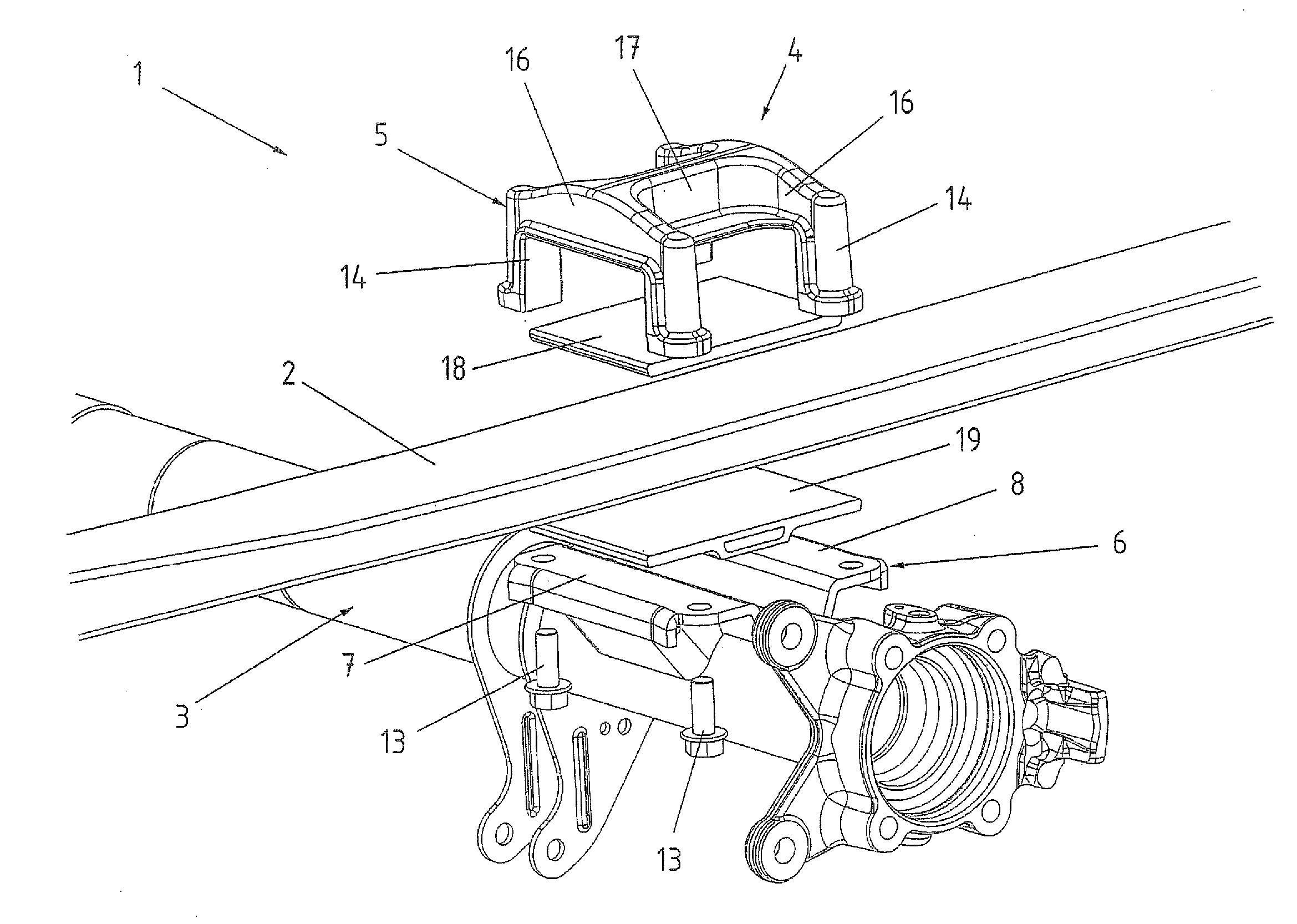
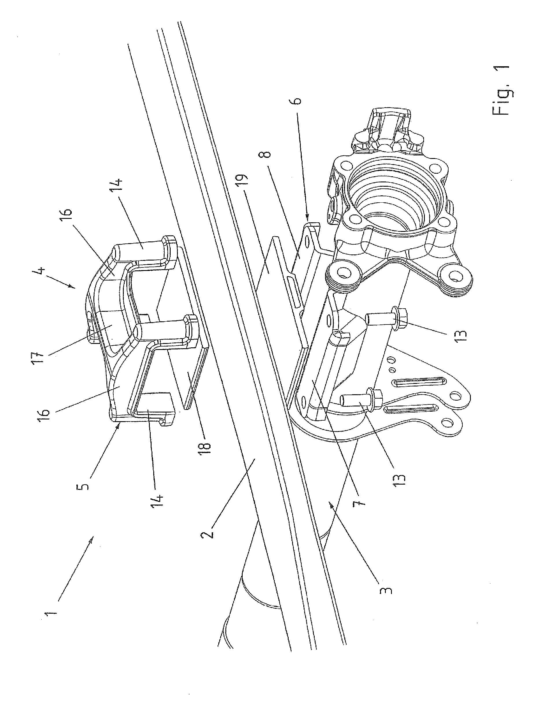
[0027]Turning now to the drawing, and in particular to FIG. 1, there is shown an exploded view of a leaf spring attachment according to the present invention, generally designated by reference numeral 1, for fixing a leaf spring 2 to a tubular axle 3 of a (not shown) chassis of a motor vehicle. In the example shown here, the leaf spring 2 is made of a glass fiber reinforced ...


PUM


Abstract

A leaf spring attachment for connecting a leaf spring to an axle or frame of a motor vehicle includes a clamp to maintain the leaf spring under tension between elastomer bodies. At least one of the elastomer bodies is connected to the leaf spring by a material joint. The clamp is split to define an upper clamp member and a lower clamp member in opposition to the upper clamp member. The upper clamp member has a U-shaped configuration to embrace a topside and opposite length sides of the leaf spring. The lower clamp member includes a plurality of retention plates in spaced-apart relationship for connection with the axle by material joint. Screw fasteners are provided to secure legs of the upper clamp member to the lower clamp member.

Description

CROSS-REFERENCES TO RELATED APPLICATIONS[0001]This application claims the priority of German Patent Application, Serial No. 10 2010 010 987.8-21, filed Mar. 10, 2010, pursuant to 35 U.S.C. 119(a)-(d), the content of which is incorporated herein by reference in its entirety as if fully set forth herein.BACKGROUND OF THE INVENTION[0002]The present invention relates to a leaf spring attachment to secure a leaf spring to an axle or frame of a motor vehicle.[0003]The following discussion of related art is provided to assist the reader in understanding the advantages of the invention, and is not to be construed as an admission that this related art is prior art to this invention.[0004]Leaf springs made of composite material such as glass fiber-reinforced plastic (GFRP) or carbon reinforced plastic (CRP), or of steel are normally installed to the rear axles of a motor vehicle by a forced engagement so as maintain the leaf spring under tension via tensioning clips, so called spring clips, o...

Claims


Application Information

Patent Timeline
Patent Type & Authority Applications(United States)
IPC IPC(8): B60G11/113F16F1/26
CPCB60G9/003B60G11/04F16F1/30B60G2202/112B60G2204/4306B60G2200/31
Inventor HENKSMEIER, THOMASHOCHAPFEL, ERIK
Owner BENTELER AUTOMOBILTECHNIK GMBH
Why Eureka
Try Eureka