
Variable on-time control method for high light-load efficiency, small output voltage ripple, and audible-noise-free operation

a technology of on-time control and light-load efficiency, which is applied in the direction of dc-dc conversion, electric vehicles, transportation and packaging, etc., can solve the problems of prolonging the time that the primary switching element stays, slowing the charging rate of the charge storage device, etc., and achieves low output voltage ripple, low cost, and low cost

Inactive Publication Date: 2011-09-08
SEMTECH CORP
View PDF2 Cites 4 Cited by
  • Summary
  • Abstract
  • Description
  • Claims
  • Application Information

AI Technical Summary

Benefits of technology

[0007]An apparatus and method of controlling power converters is achieved that produces high light-load efficiency and reduced output voltage ripple while maintaining quiet operation that is free from audible noise. The inventive method is applicable to a wide variety of switching mode converters, including, but not limited to, boost converters, buck converters, buck-boost converters, single-ended primary inductor (SEPIC) converters, and other converter topologies, both isolated and non-isolated.
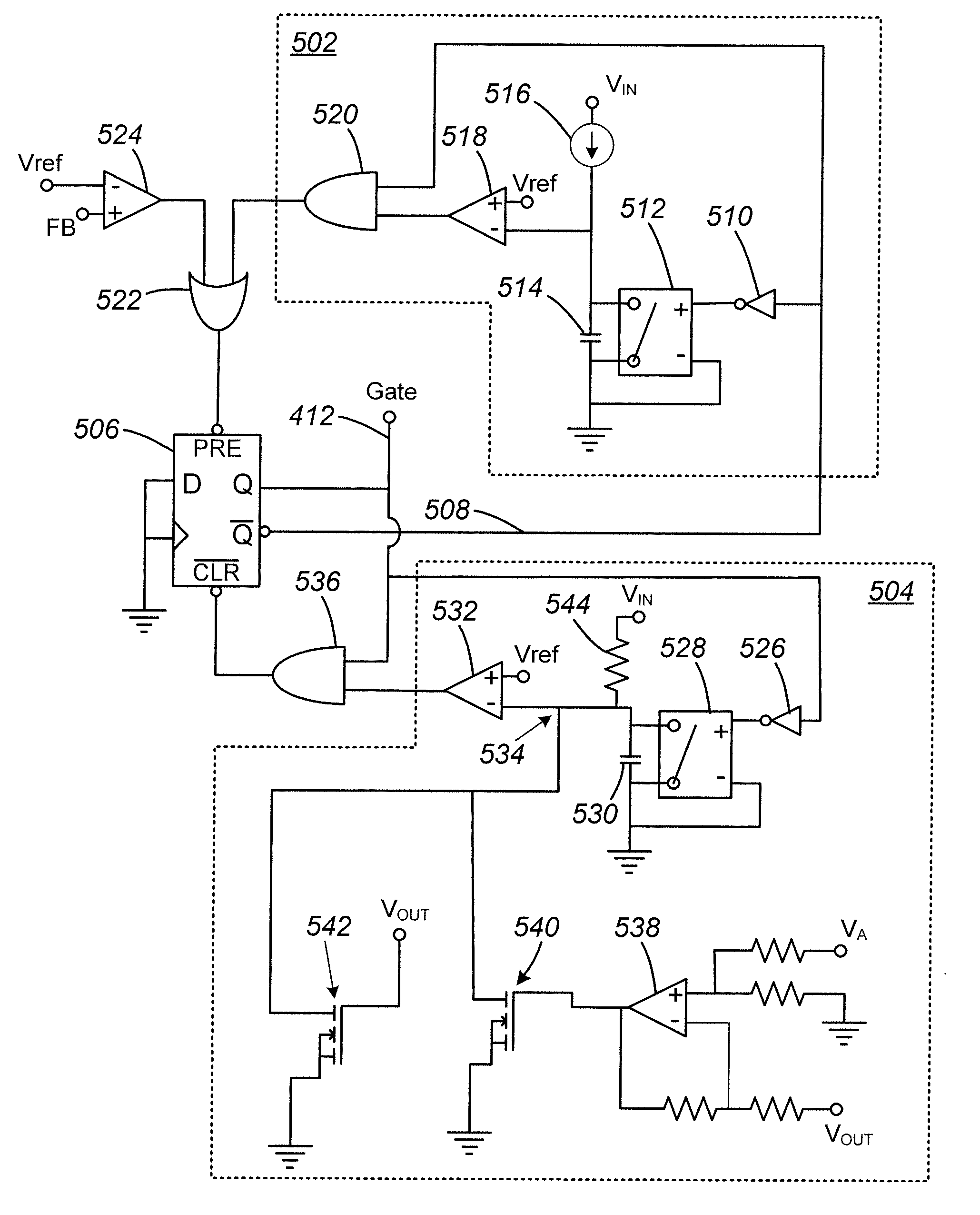
[0010]However, the primary switching element can be turned off later or earlier than would be expected by the addition of one or more variable control circuits connected to the current source. A first variable control circuit adjusts the on time of the primary switching element in accordance with the load current and the output voltage of the switching power converter. A current sense voltage proportional to the bad current is scaled and compared in a differential amplifier with a scaled version of the power converter output voltage. The output of the differential amplifier is used to drive a transconductance amplifier, which may be a MOSFET, that is connected to the current source. Thus, as the load current increases, the transconductance amplifier shunts an increasing amount of current from the current source, slowing the charging rate of the charge storage device, and prolonging the time that the primary switching element stays on.
[0011]A second variable control element includes a second transconductance amplifier that is similarly connected to the current source but that has an input connected to the output voltage of the switching power converter. Thus, as the output voltage increases, the amount of current from the current source that is shunted through the second transconductance amplifier increases, and the charge rate of the charge storage device decreases, increasing the on time of the primary switching element.
[0013]A minimum off-time circuit may further be added to the system in accordance with another embodiment of the present invention. The minimum off-time circuit includes a second charge storage device that is charged by a second current source, which may similarly be a resistor in series with the input voltage of the switching power converter. A bypass switch is disposed in parallel with the second charge storage device such that the second charge storage device charges through the current source when the bypass switch is opened. The voltage of the charge storage device is compared to a reference voltage. The output of the comparison circuit is used to hold the primary switching element of the power converter in the off state until the comparison circuit changes state, indicating that the voltage of the second charge storage device exceeds the reference voltage. This circuit thus ensures that the main switching element remains off for a minimum time period.

Problems solved by technology

Thus, as the load current increases, the transconductance amplifier shunts an increasing amount of current from the current source, slowing the charging rate of the charge storage device, and prolonging the time that the primary switching element stays on.

Method used


Image

  • Variable on-time control method for high light-load efficiency, small output voltage ripple, and audible-noise-free operation
  • Variable on-time control method for high light-load efficiency, small output voltage ripple, and audible-noise-free operation
  • Variable on-time control method for high light-load efficiency, small output voltage ripple, and audible-noise-free operation

Examples


Embodiment Construction

[0023]The present invention relates to an apparatus and method for controlling a switching converter to achieve high light-load efficiency while maintaining quiet operation free from audible noise. Output voltage ripple is also greatly reduced. The inventive method is applicable to a wide variety of power converter architectures, including boost, buck, buck-boost, SEPIC, and other topologies, both isolated and non-isolated.

[0024]FIG. 3 is a conceptual circuit diagram illustrating a method of variable on-time control of a boost converter in accordance with an embodiment of the present invention. A boost converter similar to that of FIG. 1 is shown with an additional control block 302 that provides the ability to control the on-time of MOSFET 108 in a variable manner. In such a boost converter, the governing equation provides two possible ways in which the on-time-control block 302 may be used to provide variable on-time control. Manipulating the boost converter equation presented ear...


PUM


Abstract

An apparatus and method of controlling power converters is achieved that produces high light-load efficiency and reduced output voltage ripple while maintaining quiet operation that is free from audible noise. The inventive method includes a variable on-time control circuit that is applicable to a wide variety of switching mode converters, including, but not limited to, boost converters, buck converters, buck-boost converters, single-ended primary inductor (SEPIC) converters, and other converter topologies, both isolated and non-isolated.

Description

BACKGROUND OF THE INVENTION[0001]1. Field of the Invention[0002]The invention relates generally to the field of switching power converters, and more particularly, to control methods that enable power converters to achieve reduced output voltage ripple and high light-load efficiency while maintaining quiet operation, free from audible noise.[0003]2. Description of Related Art[0004]A switching power converter control system, typical of the prior art, can be characterized as constant on-time control. FIG. 1 is a simplified schematic of a boost converter employing constant on-time control. Vin is the input voltage 102, and Vo is the output voltage 112. The input inductor 104 has an equivalent series resistance (ESR) of RL, represented by resistor 106. Under the constant on-time control method, the MOSFET 108 is turned on for a duration Ton, and then turned off for a duration Toff that is determined by a feedback voltage that is developed by the resistive divider formed by resistor 116 a...

Claims


Application Information

Patent Timeline
Patent Type & Authority Applications(United States)
IPC IPC(8): H02J7/00
CPCH02J7/00H02M1/0032H02M3/1566H02M3/156
Inventor CHANG, CHINCHANG, VETER
Owner SEMTECH CORP
Learn More