
Device for fixing a temperature sensor

a technology for temperature sensors and devices, applied in the field of systems for fixing sensors, can solve the problems of ntc thermal decoupling, extremely unfavorable heat transfer characteristics, and specific weakening of the ntc to the sensor housing of the pressure/temperature sensor, so as to improve heat transfer, shorten response times, and increase flow rate

Active Publication Date: 2011-09-01
ROBERT BOSCH GMBH
View PDF12 Cites 17 Cited by
  • Summary
  • Abstract
  • Description
  • Claims
  • Application Information

AI Technical Summary

Benefits of technology

[0008]An object of the present invention is to cause the flow to be specifically accelerated, resulting in a higher flow rate in the area of the NTC, accompanied by an improved heat transfer and the shorter response times resulting therefrom.
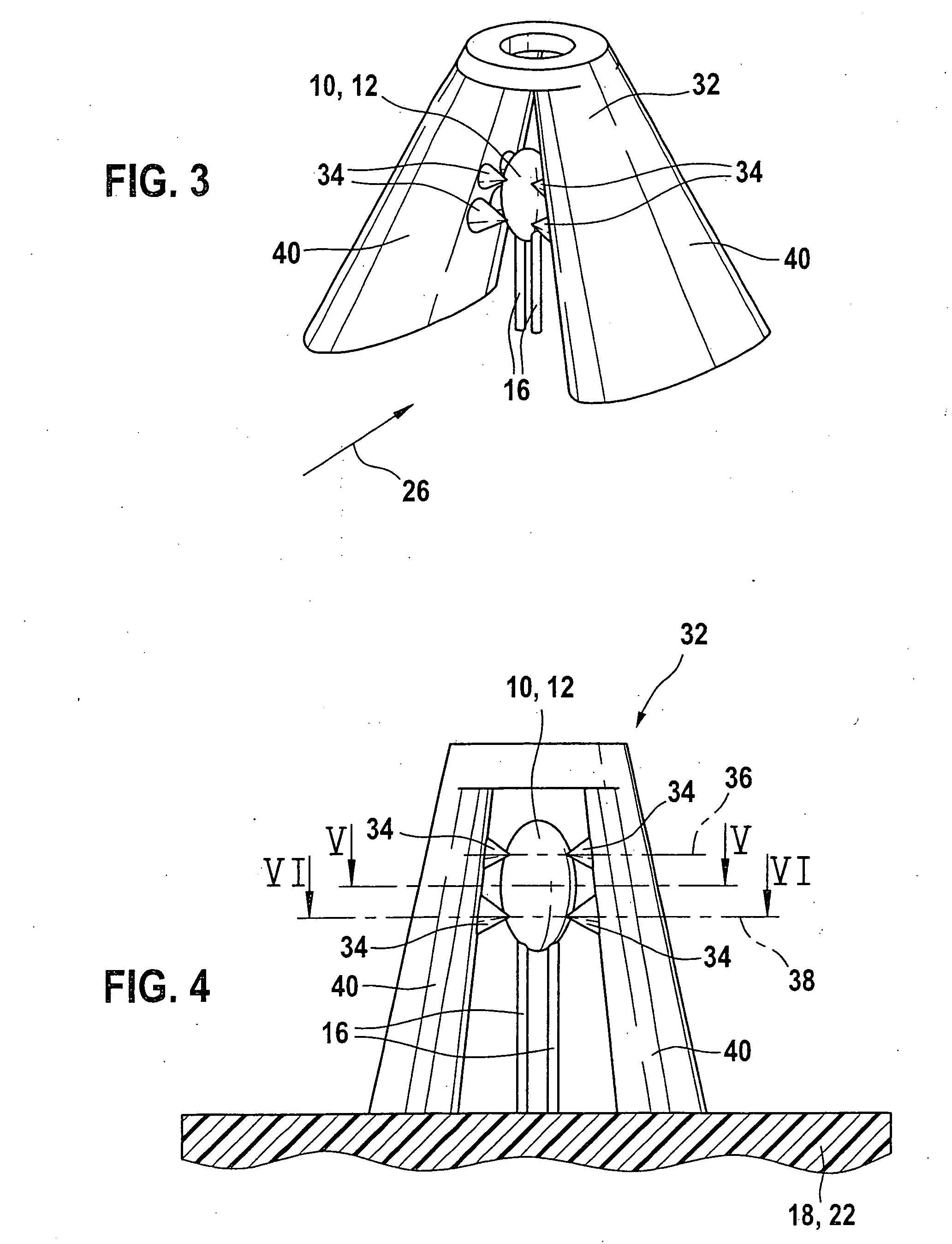
[0010]A cage surrounding the NTC is designed in such a way that the NTC is specifically placed in a zone having high flow rates. To that end, lateral “walls” of the protective cage are provided with a droplet-shaped profile which is designed similarly to the wings of an airplane. This profile accelerates the flow locally and specifically diverts it to the head of the NTC. In addition to the flow acceleration, the NTC cage must assume an important protective function for the NTC by fixing the head of the NTC and protecting it from mechanical influences. Furthermore, an additional protective function is that the NTC is prevented from experiencing flow-induced vibrations. To fulfill these requirements, the NTC is guided and the thermal connection of the same to the housing of the sensor and the cage surrounding the NTC is simultaneously designed to be as weak as possible. This in turn makes it possible to ensure that the NTC head is only fixed via thin, peaked mandrels having extremely unfavorable heat transfer characteristics.

Problems solved by technology

Furthermore, the thermal connection of the NTC to the sensor housing of the pressure / temperature sensor is specifically weakened or the NTC is thermally decoupled from the sensor housing.
This in turn makes it possible to ensure that the NTC head is only fixed via thin, peaked mandrels having extremely unfavorable heat transfer characteristics.

Method used


Image

  • Device for fixing a temperature sensor
  • Device for fixing a temperature sensor
  • Device for fixing a temperature sensor

Examples


Embodiment Construction

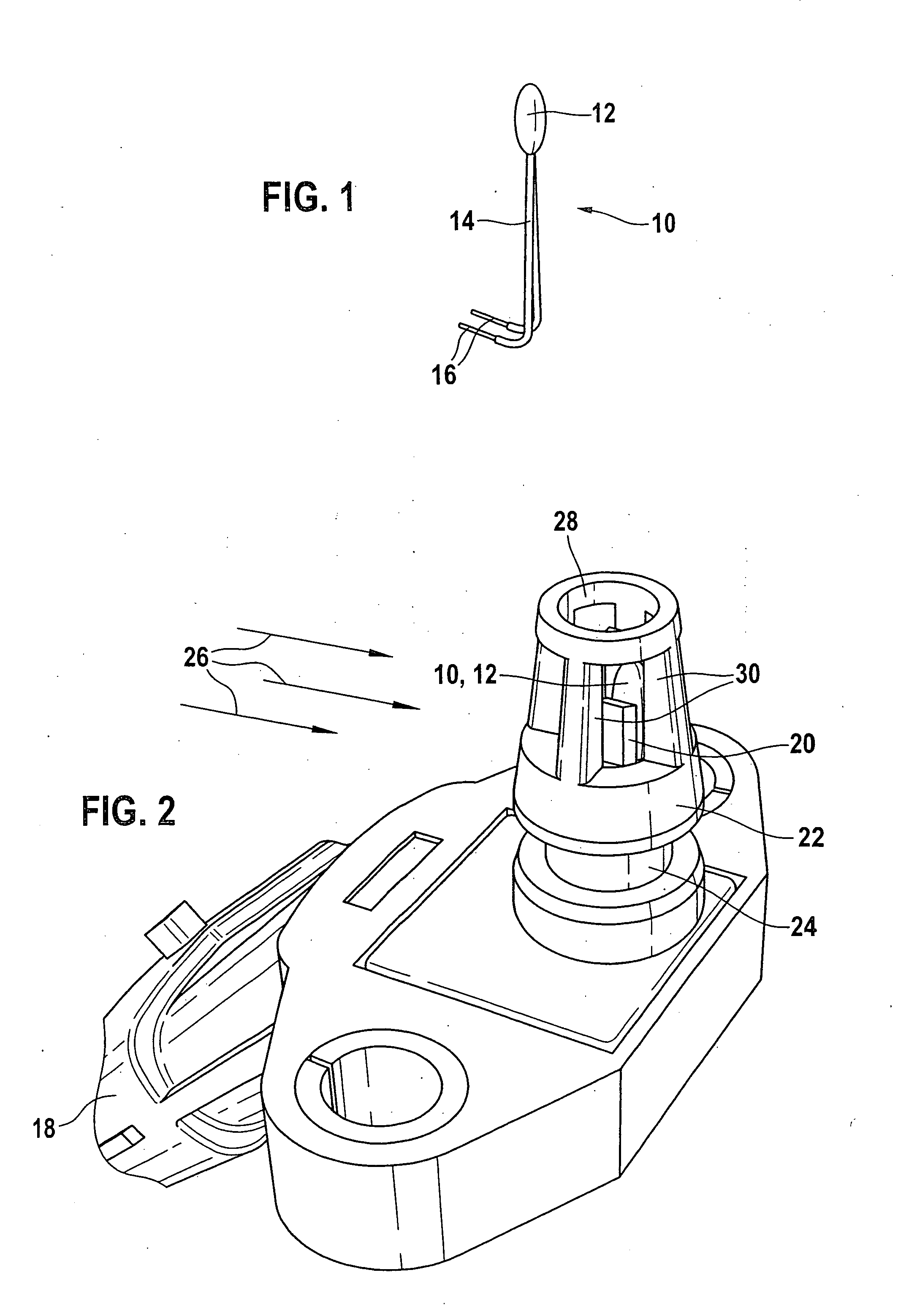
[0028]A temperature sensor designed in particular as an NTC element is seen in the representation according to FIG. 1.

[0029]As FIG. 1 shows, temperature sensor 10 includes a head 12 having connecting pins 16 for signal transmission. Temperature sensor 10, designed as an NTC element, is a temperature-dependent resistor which varies with the temperature. Head 12 of temperature sensor 10 is normally manufactured as a smooth, large glass or plastic bead having a diameter of approximately 1 mm to 3 mm.

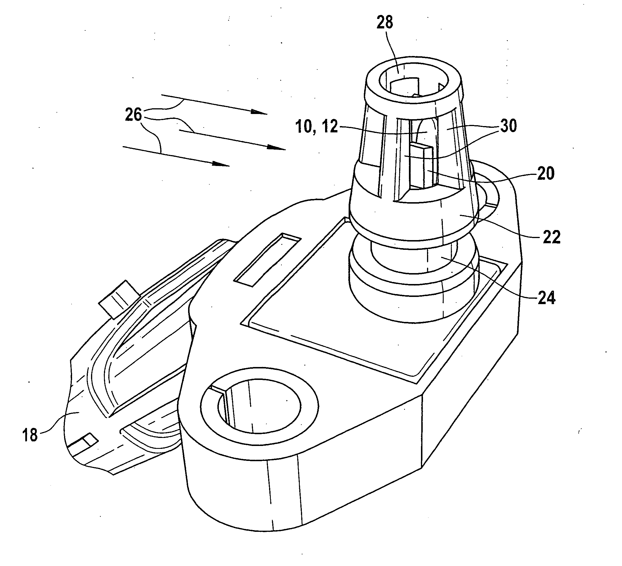
[0030]The representation according to FIG. 2 shows a part of a sensor housing having a pressure connector formed on it, temperature sensor 10 being embedded in the pressure connector.

[0031]The representation according to FIG. 2 shows that temperature sensor 10 which, as already indicated in FIG. 1, is extremely sensitive mechanically, is enclosed by a support 20 on pressure connector 22, which is part of a sensor housing 18. As represented in FIG. 2, temperature sensor 10, which is exposed ...


PUM

PropertyMeasurementUnit
sizeaaaaaaaaaa
temperatureaaaaaaaaaa
diameteraaaaaaaaaa

Abstract

In a system for attaching and fixing a temperature sensor, e.g., an NTC element, the NTC element is accommodated in a pressure connector section of a sensor housing. The area of the head of the temperature sensor is flanked and / or supported by guide vanes, which cause the incident flow in the area of the head of the temperature sensor to be accelerated.

Description

BACKGROUND OF THE INVENTION[0001]1. Field of the Invention[0002]The present invention relates to a system for fixing a sensor in a housing.[0003]2. Description of the Related Art[0004]Published German patent application document DE 197 31 420 A1 describes a device for detecting the pressure and the temperature in the intake manifold of an internal combustion engine and a method for manufacturing it. A temperature sensor and a pressure sensor fastened together with an evaluation circuit to a substrate with as little stress as possible are situated in a shared housing. The housing includes at least two spaces separated from one another, one of which forms a pressure space which is sealed off from the environment and is connected to the intake manifold via a connector, the part of the substrate on which the pressure sensor is attached being situated in the first space, and the second of which is used for accommodating and fastening the remaining part of the substrate having connecting ...

Claims


Application Information

Patent Timeline
Patent Type & Authority Applications(United States)
IPC IPC(8): G01K1/14
CPCG01K1/14G01K2205/02G01K2013/024G01K13/02G01K13/024
Inventor GMELIN, CHRISTOPHHERRMANN, REINHOLD
Owner ROBERT BOSCH GMBH
Learn More