
Rotary waterfall shower

Active Publication Date: 2011-09-01
XIAMEN SOLEX HIGH TECH IND CO LTD
View PDF8 Cites 11 Cited by
  • Summary
  • Abstract
  • Description
  • Claims
  • Application Information

AI Technical Summary

Benefits of technology

[0004]The object of the present invention is to provide a rotary waterfall shower with rotatable water outlet and overcome the shortages of the conventional technique. Water sprinkled out from the water outlet of the rotary waterfall shower can be dynamically rotated to form gainly clusters of spiral waterfall water blooms, and the shower has the effect of gentle massage.
[0008]The center hole of each output gear wheel is fixedly connected with the water discharge component in an axial direction. Alternatively, the vane wheels can also be arranged vertically, and then the water discharge components can be horizontally rotate in front of the front cover by the worm and gear. However, such structure is more complex, the shower may be easily broken during the operation.
[0013]There are interval pillars disposed oppositely on the front end of the output gear wheels and correspond to the periphery of the center hole, so the water can flow into the water nozzle of the water discharge components through the intervals between the pillars, thus better washing effects are achieved.
[0015]The diameter of the output gear wheel is greater than the diameter of pinion wheel fixedly disposed on the front end of the vane wheels, so that the rotating speed of the water discharge component can be reduced.

Problems solved by technology

In the conventional shower, its water outlet is generally designed with a plurality of water nozzles, said water nozzles can only applied for distributing the water outflow from the water outlets, when the user uses the conventional shower, the water will be sprinkled from the water nozzles and form a water column with great pressure, so the user may feel uncomfortable when the water column hits him.
The user can only adjust the amount of the water outflow to reduce the pressure of the water column, however, the bath may not be quite effective since the amount of the water outflow is greatly reduced, therefore said conventional shower with single function can not satisfy the requirements of the consumer.
Although shower with massage function have already been invented, it need to arrange an electric motor in the shower chamber in a sealing way, so it may be unsafe in the operation.

Method used


Image

  • Rotary waterfall shower
  • Rotary waterfall shower
  • Rotary waterfall shower

Examples


embodiment 1

[0025]The present invention will become clear with the reference of the detailed description of the embodiments and the accompanying drawings.

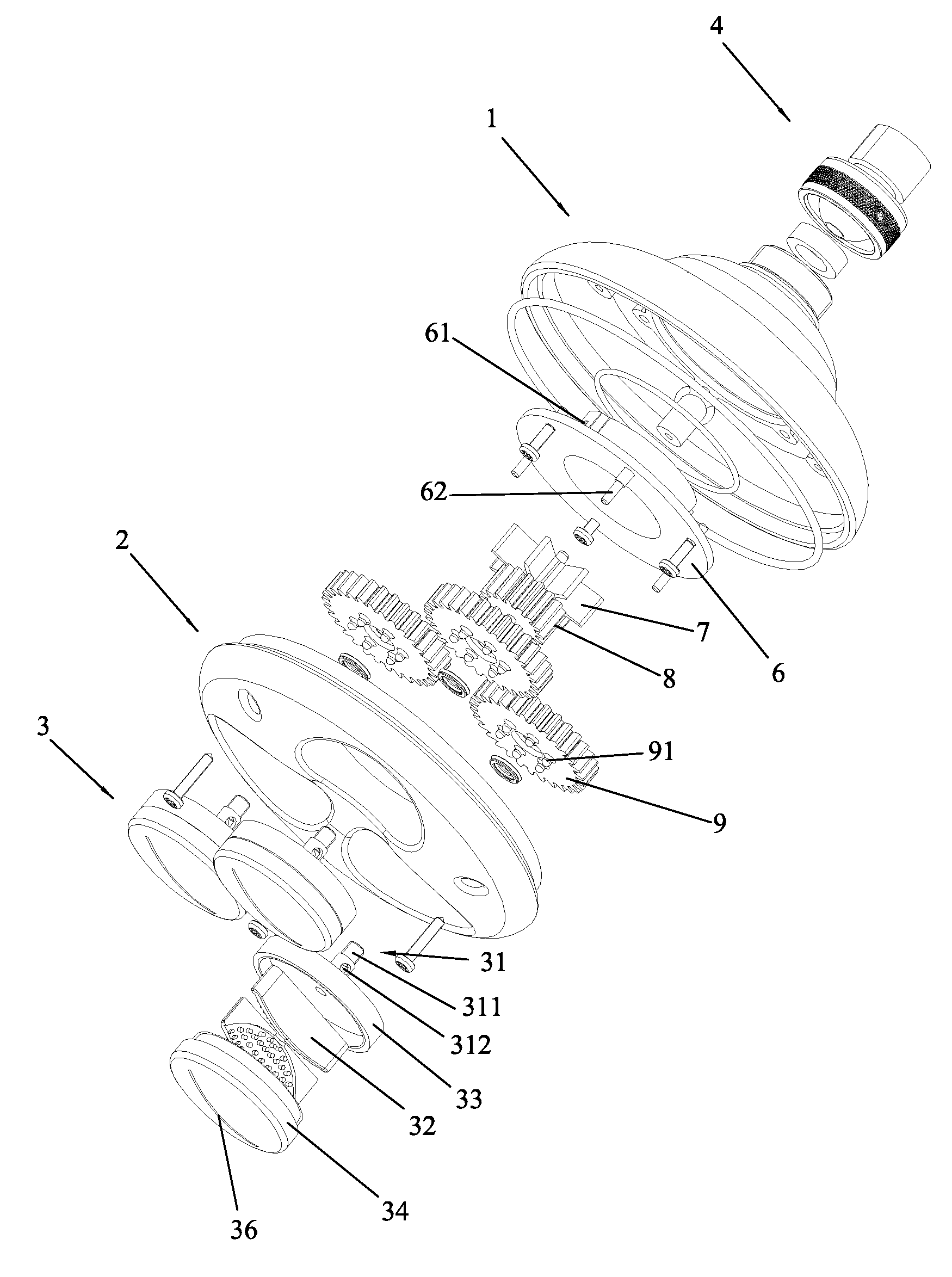
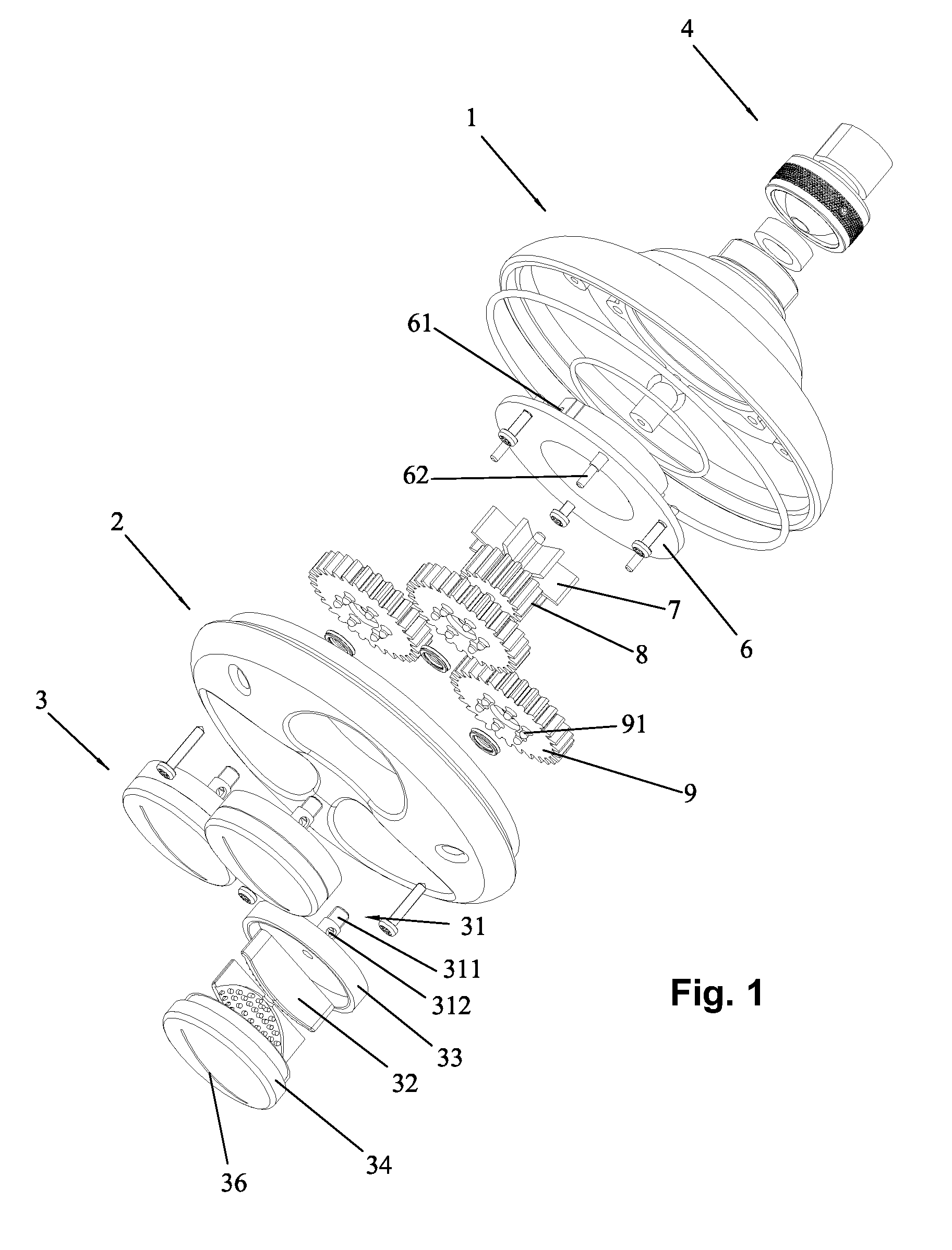
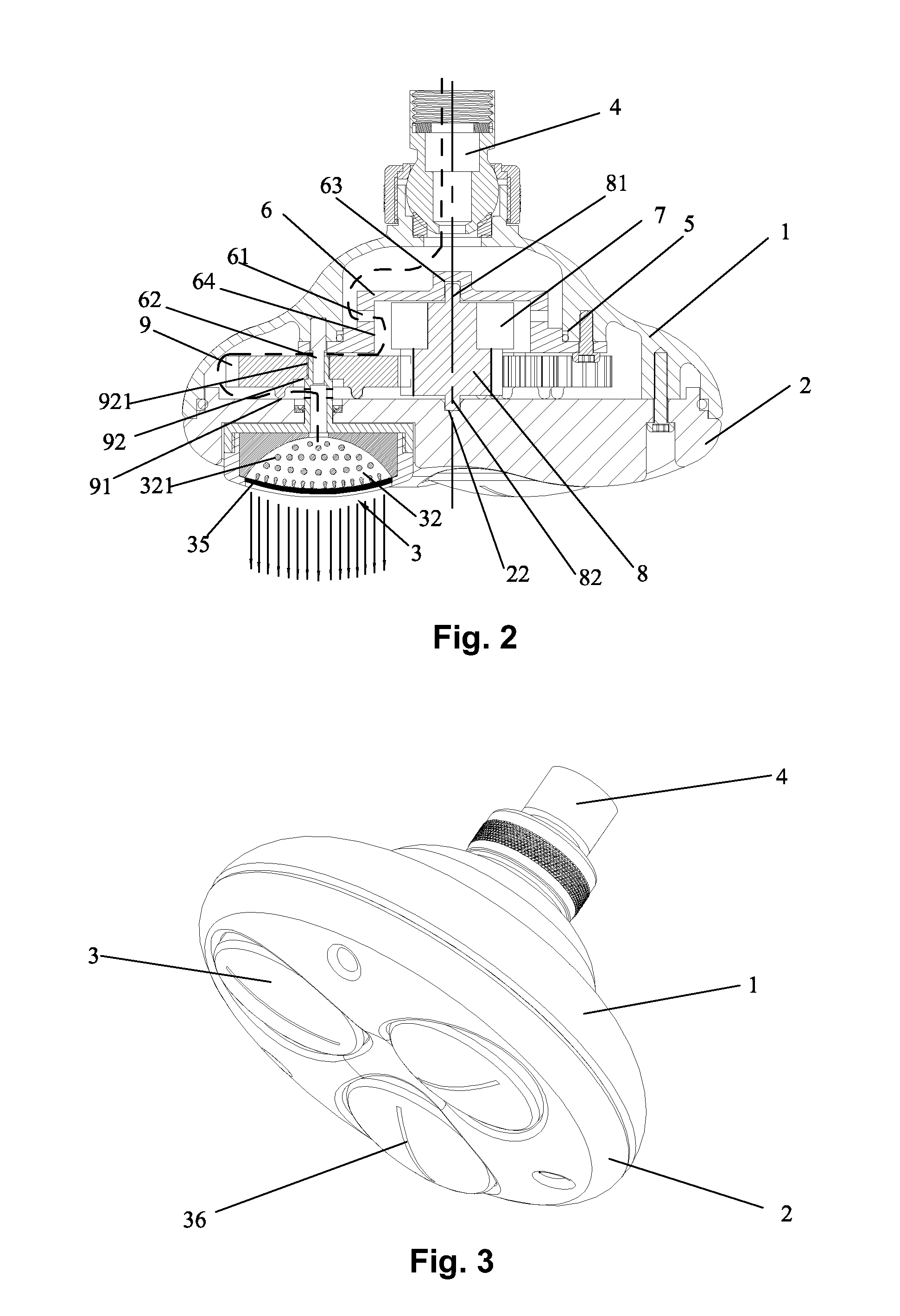
[0026]The rotary waterfall shower, comprising a hollow body 1, a front cover 2, water discharge components 3, a joint head 4, a water division member 5, vane wheels 7, a pinion wheel 8 and output gear wheels 9, the front cover 2 is fixed on the front of the body 1 after being spaced by a sealing ring. the water division member 6 with an oblique spray hole 61 is fixed in the body 1 after being spaced by a sealing ring 5, a pinion wheel 8 is fixedly arranged on the front end of the vane wheels 7 in an axial direction, two rotary shafts 81 and 82 are disposed on the two ends of the vane wheels 7, shaft seats 63, 62 are respectively disposed on the center of the water division member 6 and the front cover 2 and respectively matched with the water division member 6 and the front cover 2, the vane wheels 7 cooperate with the shaft seats 63, 62 on th...


PUM


Abstract

The invention discloses a rotary waterfall shower comprising a hollow body, transversely arranged vane wheels, a front cover arranged on the front end of the body in a sealing way and a water division member which is arranged in the body in a sealing way and can cause the vane wheels to rotate, a pinion wheel is fixedly arranged on the front end of the vane wheels in an axial direction and is meshed with output gear wheels distributed in a central symmetry way, and each output gear wheel can drive one rotary water discharge component arranged on the front end of the front cover to rotate horizontally. Water sprinkled out from the water outlet of the rotary waterfall shower can be dynamically rotated to form gainly clusters of spiral waterfall water blooms, and the shower has the effect of gentle massage.

Description

FIELD OF THE INVENTION[0001]The present invention relates to a shower, especially to a rotary waterfall shower whose water outlet can rotate.BACKGROUND OF THE INVENTION[0002]In the conventional shower, its water outlet is generally designed with a plurality of water nozzles, said water nozzles can only applied for distributing the water outflow from the water outlets, when the user uses the conventional shower, the water will be sprinkled from the water nozzles and form a water column with great pressure, so the user may feel uncomfortable when the water column hits him. The user can only adjust the amount of the water outflow to reduce the pressure of the water column, however, the bath may not be quite effective since the amount of the water outflow is greatly reduced, therefore said conventional shower with single function can not satisfy the requirements of the consumer.[0003]In order to overcome the above shortages, it needs to change the water output effects of the existing sh...

Claims


Application Information

Patent Timeline
IPC IPC(8): B05B3/02
CPCB05B1/044B05B3/0422B05B1/14B05B1/18
Inventor CHEN, TIANYU
Owner XIAMEN SOLEX HIGH TECH IND CO LTD
Learn More