
Method for manufacturing of ceramic brake disk rotor with internal cooling channel

a technology of ceramic brake discs and cooling channels, which is applied in the direction of brake discs, mechanical devices, bandages, etc., can solve the problems of warp or dimensional change, and the selection of materials having a shape of cooling channels b>10/b> is very restrictive, so as to achieve the shape of cooling channels more economically and easily, improve the performance of disk rotors, and enhance the dimensional precision of cooling channels

Inactive Publication Date: 2011-09-01
DACC
View PDF3 Cites 2 Cited by
  • Summary
  • Abstract
  • Description
  • Claims
  • Application Information

AI Technical Summary

Benefits of technology

[0022]According to a method of manufacturing a ceramic brake disk rotor according to the present invention, it is possible to realize a shape of cooling channels more economically and easily.
[0023]Furthermore, according to a method of manufacturing a ceramic brake disk rotor according to the present invention, the dimensional precision of cooling channels is enhanced, thereby having an effect of improving the performance of a disk rotor.

Problems solved by technology

However, a warp or dimensional change is also created during a thermal treatment process step by such a method, and additional processes are required, thereby having a problem similar to the first method.
However, such a method also has a disadvantage that the selection of a material having a shape of the cooling channels 10 is very restrictive.

Method used


Image

  • Method for manufacturing of ceramic brake disk rotor with internal cooling channel
  • Method for manufacturing of ceramic brake disk rotor with internal cooling channel
  • Method for manufacturing of ceramic brake disk rotor with internal cooling channel

Examples


first embodiment

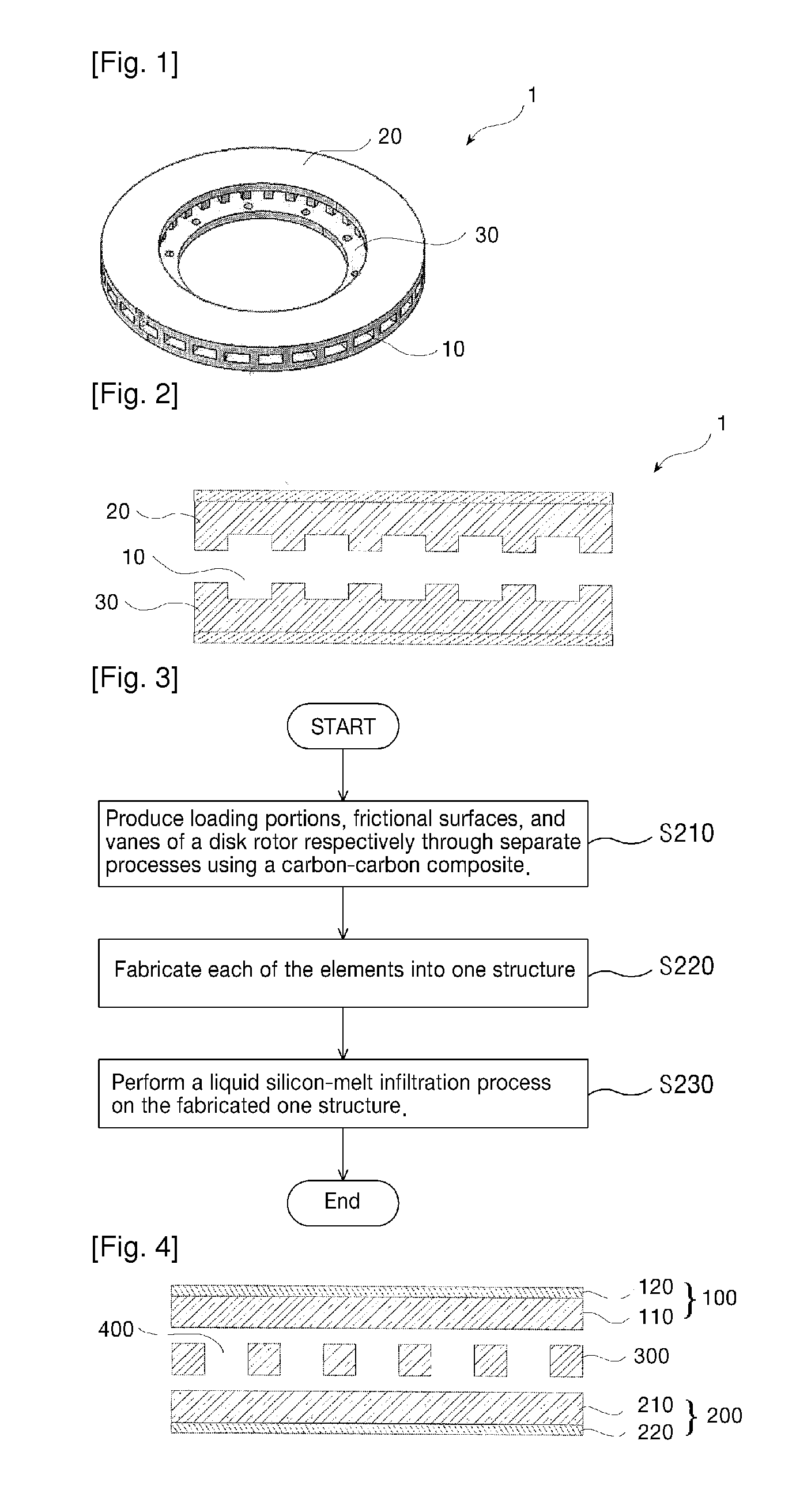
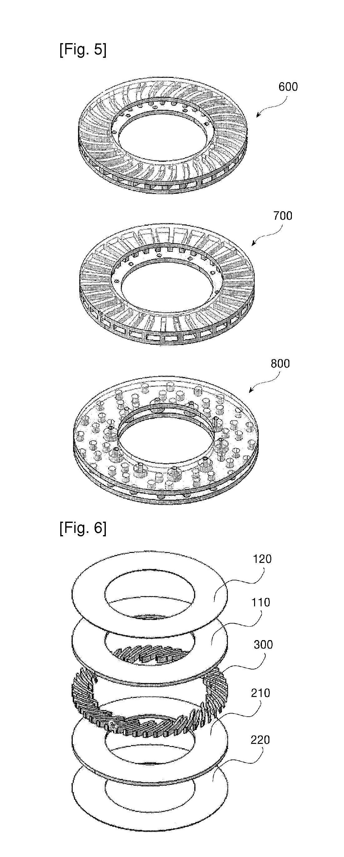
[0033]FIG. 3 is a flowchart for explaining a method of manufacturing a ceramic brake disk rotor having internal cooling channels according to a first embodiment of the present invention, and FIG. 4 is a view illustrating each element applied to a method of manufacturing a disk rotor of the present invention.

[0034]Referring to FIGS. 3 and 4, a method of manufacturing a ceramic brake disk rotor having internal cooling channels according to the present invention, includes a step S210 of producing loading portions 110, 210, frictional surfaces 120, 220, and vanes 300 of the disk rotor respectively through separate processes using a carbon fiber reinforced carbon-carbon composite, a step S220 of fabricating the loading portions 110, 210, frictional surfaces 120, 220, and vanes 300 respectively produced through separate processes into one structure, and a step S230 of performing a liquid silicon-melt infiltration process on the fabricated one structure.

[0035]The step S210 of producing loa...

second embodiment

[0051]The method of manufacturing a ceramic brake disk rotor having internal cooling channels according to a second embodiment of the present invention is similar to the configuration of the first embodiment, except that the loading portions 110, 210 of the first embodiment have a function of the frictional surfaces 120, 220 while the frictional surfaces 120, 220 are omitted. Furthermore, in the second embodiment of the invention, the same reference numerals are assigned to the same elements as those in the first embodiment, and their explanation will be omitted.

[0052]FIG. 9 is a flowchart for explaining a method of manufacturing a ceramic brake disk rotor having internal cooling channels according to a second embodiment of the present invention.

[0053]Referring to FIG. 9, a method of manufacturing a ceramic brake disk rotor having internal cooling channels, according to a second embodiment of the present invention, includes a step S610 of producing an upper loading portion 110, a lo...


PUM

PropertyMeasurementUnit
lengthaaaaaaaaaa
frictional coefficientaaaaaaaaaa
compositionaaaaaaaaaa

Abstract

The present invention relates to a method of more precisely and easily realizing cooling channels constituting a ceramic brake disk rotor. In order to achieve an object of the invention, there is provided a method of manufacturing a ceramic brake disk rotor having internal cooling channels, comprising the steps of: (a) producing loading portions 110, 210, frictional surfaces 120, 220, and vanes 300 of the disk rotor respectively through separate processes using a carbon fiber reinforced carbon-carbon composite; (b) fabricating the loading portions 110, 210, frictional surfaces 120, 220, and vanes 300 respectively produced through separate processes into one structure and (c) performing a liquid silicon-melt infiltration process for the fabricated one structure. According to the present invention, a shape of the cooling channel can be economically and easily realized, and furthermore the dimensional precision of the cooling channel is enhanced, thereby having an effect of improving the performance of the disk rotor.

Description

TECHNICAL FIELD[0001]The present invention relates to a method of manufacturing a ceramic brake disk rotor having internal cooling channels, and more particularly, to a method of more precisely and easily realizing cooling channels constituting a ceramic brake disk rotor.BACKGROUND ART[0002]In general, brake systems are mostly foot brakes in a manner that are actuated by foot control through a driver, as a device for slowing down or stopping a car while driving, and the actuating force of the driver, i.e., pedal force is converted to the braking force of a wheel through the medium of hydraulic or pneumatic pressure. Of such hydraulic brakes, disk brake is mounted with a cylindrical disk rotor that is rotating along with the wheel instead of a drum to push brake pads operated by a hydraulic piston against both outer surfaces of the disk rotor, thereby braking wheels by the frictional force.[0003]The structure of the disk brake includes a disk rotor, a caliper, disk pads, and the like...

Claims


Application Information

Patent Timeline
Patent Type & Authority Applications(United States)
IPC IPC(8): B32B37/02B32B37/12B32B37/16B32B38/00B32B38/04
CPCF16D65/12F16D2065/1328F16D2200/0039Y10T156/1089F16D2250/00F16D2250/0092F16D2200/0052
Inventor IM, DONG WONCHOI, YEON HOLEE, JUN SANGKANG, JEONG SEOKSHIN, HYUN KYU
Owner DACC
Learn More