
Form And Function Helmet

a helmet and function technology, applied in the field of protection headgear, can solve the problems of unfitness, unbalanced and “unnatural” anthropometric shape, and already “top-heavy” helmets, and achieve the effects of “stabilizing/grabing bars”, aesthetics and functional, and easy helmet transportation

Inactive Publication Date: 2011-09-01
DEL ROSARIO JOHN ALEXANDER
View PDF27 Cites 3 Cited by
  • Summary
  • Abstract
  • Description
  • Claims
  • Application Information

AI Technical Summary

Benefits of technology

"The present invention is a new safety helmet design that addresses various disadvantages of prior helmet designs. It is designed to be more comfortable and easy to use for the wearer while still providing proper safety. The helmet has a component system that minimizes weight and size, and redirects or dissipates injurious rotational forces away from the head and brain. It also has improved aerodynamic qualities, better ventilation, and improved visual clarity. The helmet design includes a shell, double air intake ports, a main external visor, and numerous aerodynamic spoilers and elevations. The helmet is also designed to have flush graphics for improved visual clarity and impact. The technical effects of the invention include improved safety, comfort, and ease of use for the wearer while still providing proper safety."

Problems solved by technology

However, very little to no changes have come about in form or functionality or external design within the past 50+ years.
Traditional helmets usually have a much more pronounced jaw section with a decreasing diameter as you approach the top, this is not by any means a cosmetic choice by the manufacturers, this is a result of function due to regulatory restrictions.
What you get is a terribly unbalanced and “Unnatural” anthropometric shape.
Should they attempt to bring the frontal area forward, it would severely affect it's already Uneven center of gravity, thus making the already “Top-heavy” helmet unbearable to withstand and unfit to wear.
Although these and other conventional helmet designs have worked well, they have failed to take into account the general dynamics in human form and / or human behavior in general.
While the motorsport and safety industry in general has evolved and improved, the helmet industry although profitable has become stagnant and mundane during all these years.
The flaw in a number of many designs is the tendency to become too similar and indistinguishable.
Crash helmets disclosed by these patents do not seem likely to provide a significant improvement over current safety helmet shells.
Also note that this configuration may also be a hindrance and a possible injury risk with consideration to rotational forces encountered during a rear head impact.
This protrusion would cause an uneven balance with the top and the bottom of the helmet causing the wearer's head to move in unintended directions.
Thus, this configuration would provide no possible benefit to the wearer.
All these aforementioned helmets do not seem likely to provide a significant improvement over current safety helmet shell design and function.

Method used


Image

  • Form And Function Helmet
  • Form And Function Helmet
  • Form And Function Helmet

Examples


Embodiment Construction

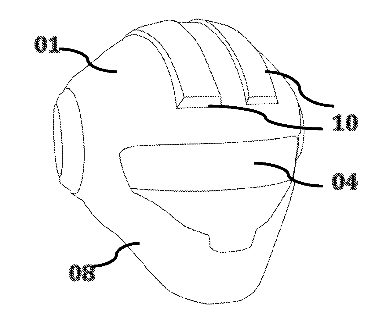
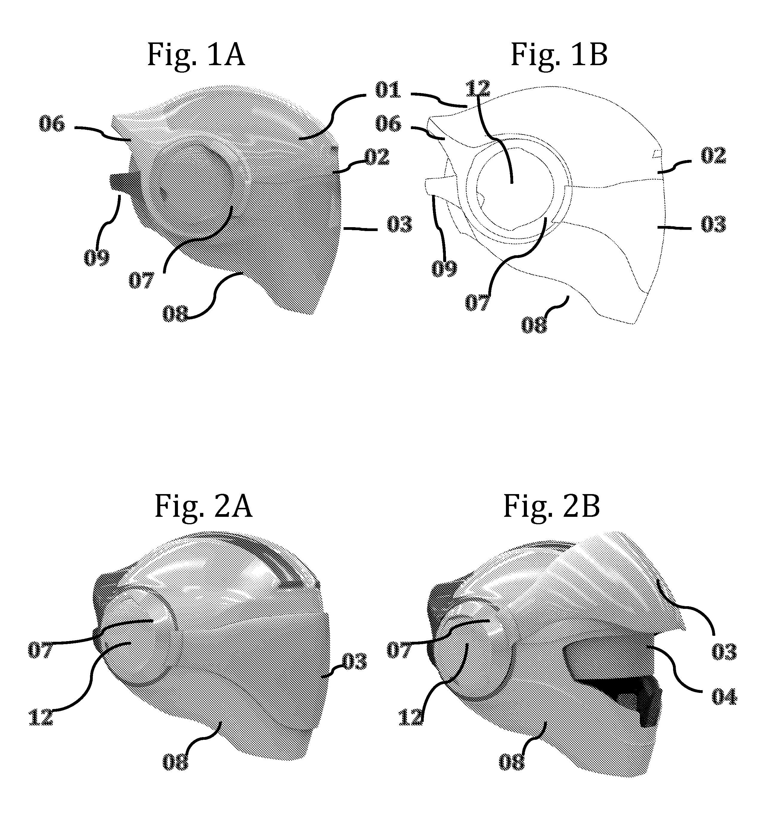
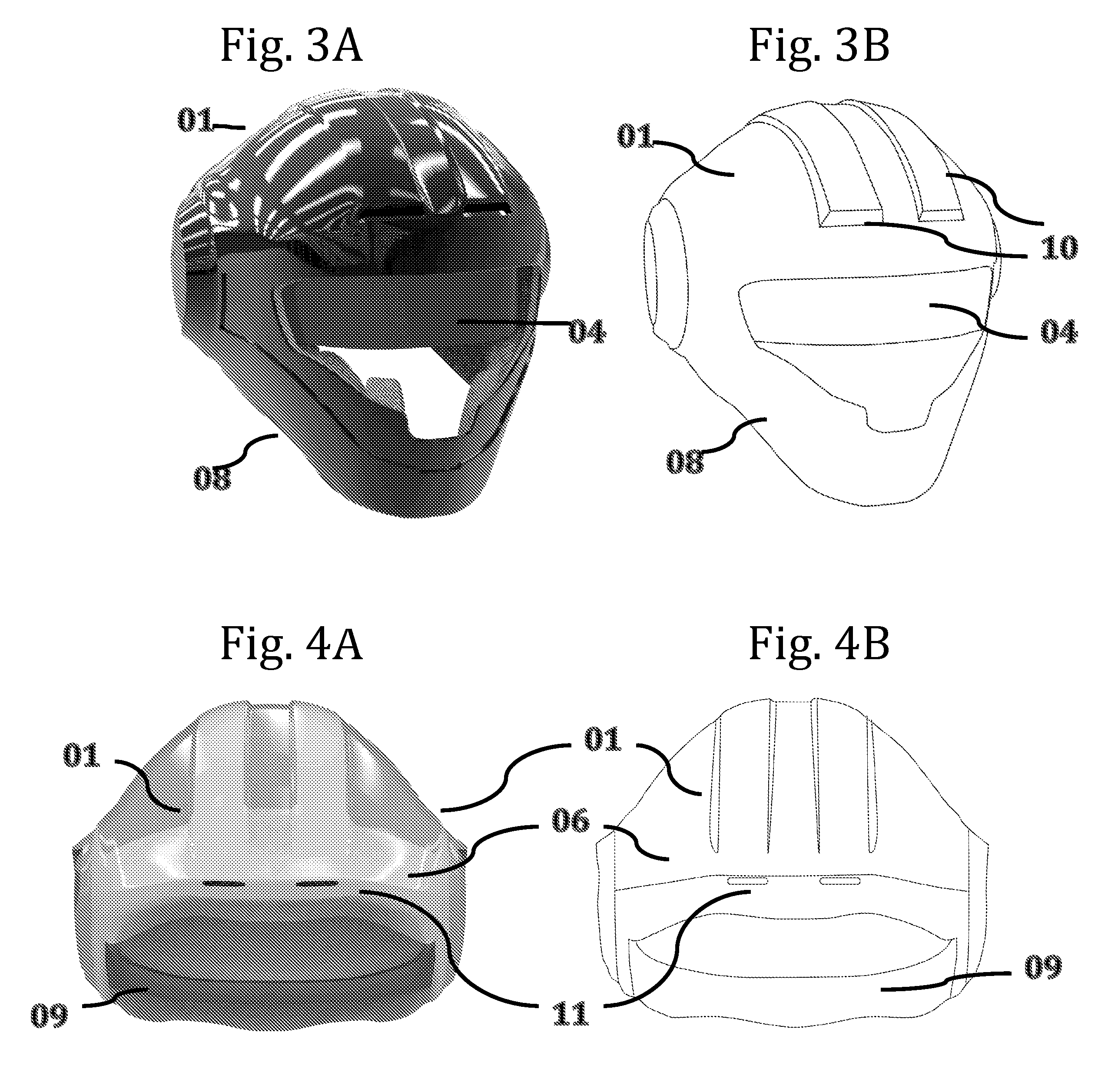
[0032]Referring now to the drawings wherein like or corresponding reference numerals are used for like or corresponding parts throughout the several views. The present invention incorporates a shell 1, herein referred to as “shell”, This shell firmly coupled with numerous components on its surface herein referred to as “components” No's 2, 3, 4, 5, 6, 7, 8, 9, 10, 11, and 12, herein referred to as “components.” Said assembly herein collectively referred to as “helmet.” The helmet may be manufactured in separate parts and processes then integrated during final assembly.

[0033]In a preferred embodiment a strong yet flexible helmet shell 1 would be the first main part. This part is thus contoured and designed to comply with certain comfort and aerodynamic parameters for optimal wearer comfort.

[0034]In a preferred embodiment the outermost layer or “shell”1 can be made up of a strong yet flexible construction preferably of fiber-reinforced composites or thermoplastics or the like with the...


PUM


Abstract

To be manufactured, formed and operated in much different and diverse fashion as compared to conventional motorsport helmets is a strong yet flexible and lightweight safety “helmet.” Comprising a “shell,” and several manually operated “components”. To be incorporated onto said shell are numerous actuating and / or fixed mechanisms with inherent safety aspects meant to increase the comfort, peripheral vision and facilitate the overall safety of the wearer. This multiplicity of independent components is also designed to protect the user's head and cranium and to reduce the violent sudden rotational forces encountered after impact. One aspect consists of a solid, continuous and unbroken “Shell.” The shell comprises a number of curves and concave segments with several other significant distinguishable design details meant to improve the overall aerodynamics of the shell. Other components include a “main external visor” and a secondary “inner visor” that actuate in multi-step processes. Aerodynamic rear and side “spoilers / elevations”, a rear “stabilizing / grab bar” for rotational force attenuation and two air “centrally mounted intake ducts” / “exhaust vents” for wearer ventilation are components that would normally be attached to this shell via commercially available adhesives and or fittings. A flush convergence of parts and components designed to work in balanced form. Presented is a much more low-profile product with a much smaller cross section in comparison to the given norm. The end result is a revolutionary product in both function and form.

Description

BACKGROUND OF THE INVENTION[0001]This invention relates generally to protective headgear and, more specifically, to a distinguishing shaped and operated motorsports helmet that improves visibility, comfort and safety to the user.[0002]Protective headgear or helmets have been worn for a long time now by individuals to protect against head injuries. The use of helmets is often a mandatory requirement for driving bicycles and certain other motor vehicles in high impact sports and in material handling and other potentially hazardous locations.[0003]The use of safety helmets has been just that—to reduce or completely protect the user from any top, lateral and penetration impact to the user's head. However, very little to no changes have come about in form or functionality or external design within the past 50+ years. Commonly used protective headgear use a hard outer casing with an impact-energy absorbing padding placed between the outer casing and the user's head. These hard casing helm...

Claims


Application Information

Patent Timeline
Patent Type & Authority Applications(United States)
IPC IPC(8): A63B71/10A42B3/22A61F9/00
CPCA42B3/061A42B3/0493A42B3/32A42B3/226
Inventor DEL ROSARIO, JOHN ALEXANDER
Owner DEL ROSARIO JOHN ALEXANDER
Learn More