Method for determining hybrid domain compensation parameters for analog loss in OFDM communication systems and compensating for the same

Inactive Publication Date: 2011-08-25
OSAKA PREFECTURE UNIV PUBLIC CORP
View PDF7 Cites 5 Cited by
  • Summary
  • Abstract
  • Description
  • Claims
  • Application Information

AI Technical Summary

Benefits of technology

[0023]The compensation method employing the OFDM scheme of the present invention enables such compensation that takes into account all types of analog losses, such as the TIQI, channel response, and CFO on the transmission side, and the RIQI and DCO on the receiver side. As a result, even with a low SNR of a received signal, it is possible not only to ensure an error rate lower than before but also to dramatically reduce the error rate with improvements in the SNR of received signals.
[0024]Furthermore, the compensation method of the present invention can analytically determine each compensation parameter. This method can drastically reduce the amount of calculation and enable higher-speed compensations when compared with a method for calculating candidate values of parameters one after another and evaluating their validity.
[0025]Furthermore, the compensation method of the present invention can analytically compensate for the I / Q imbalance. Accordingly, even an existing system which may or may not employ the OFDM scheme is allowed to calibrate the I / Q imbalance of the receiver so long as the pilot signal has a cyclic portion.

Problems solved by technology

Transmit / receive systems which employ the Orthogonal Frequency Division Multiplex (hereinafter referred to as the “OFDM”) in direct conversion transceivers suffer from degradation in transmission performance due to analog losses such as the carrier frequency offset, the transmitter / receiver I / Q imbalance, and the DC offset.
The most significant defect of the OFDM is sensitive to the CFO.
Although the DCT has tremendous merits in terms of cost and power consumption, it causes other analog losses typified by the aforementioned DC offset (DCO) and I / Q imbalance.
On the other hand, the I / Q imbalance is caused in both the transmitter and the receiver by such circuit components or local oscillators that do not ideally work.
In the OFDM system, these sorts of analog losses lead to various types of degradation in performance (see Patent Literature 5).

Method used


Image

  • Method for determining hybrid domain compensation parameters for analog loss in OFDM communication systems and compensating for the same
  • Method for determining hybrid domain compensation parameters for analog loss in OFDM communication systems and compensating for the same
  • Method for determining hybrid domain compensation parameters for analog loss in OFDM communication systems and compensating for the same

Examples


first embodiment

[0084]The present invention provides a method for compensating for the loss that an OFDM scheme signal may have when transmitted or received. In this specification, a description will be first made to the outline of a transmit / receive system and the loss that is to be compensated for according to the present invention. After that, the specification will illustrate as to how the receiver compensates for the loss. The compensation requires several compensation parameters. A description will also be made as to how to determine these parameters and how to operate on actual signals, with the OFDM signals mathematically represented. Finally, the differences between the compensation method of the present invention and the conventional compensation method will be shown by simulation.

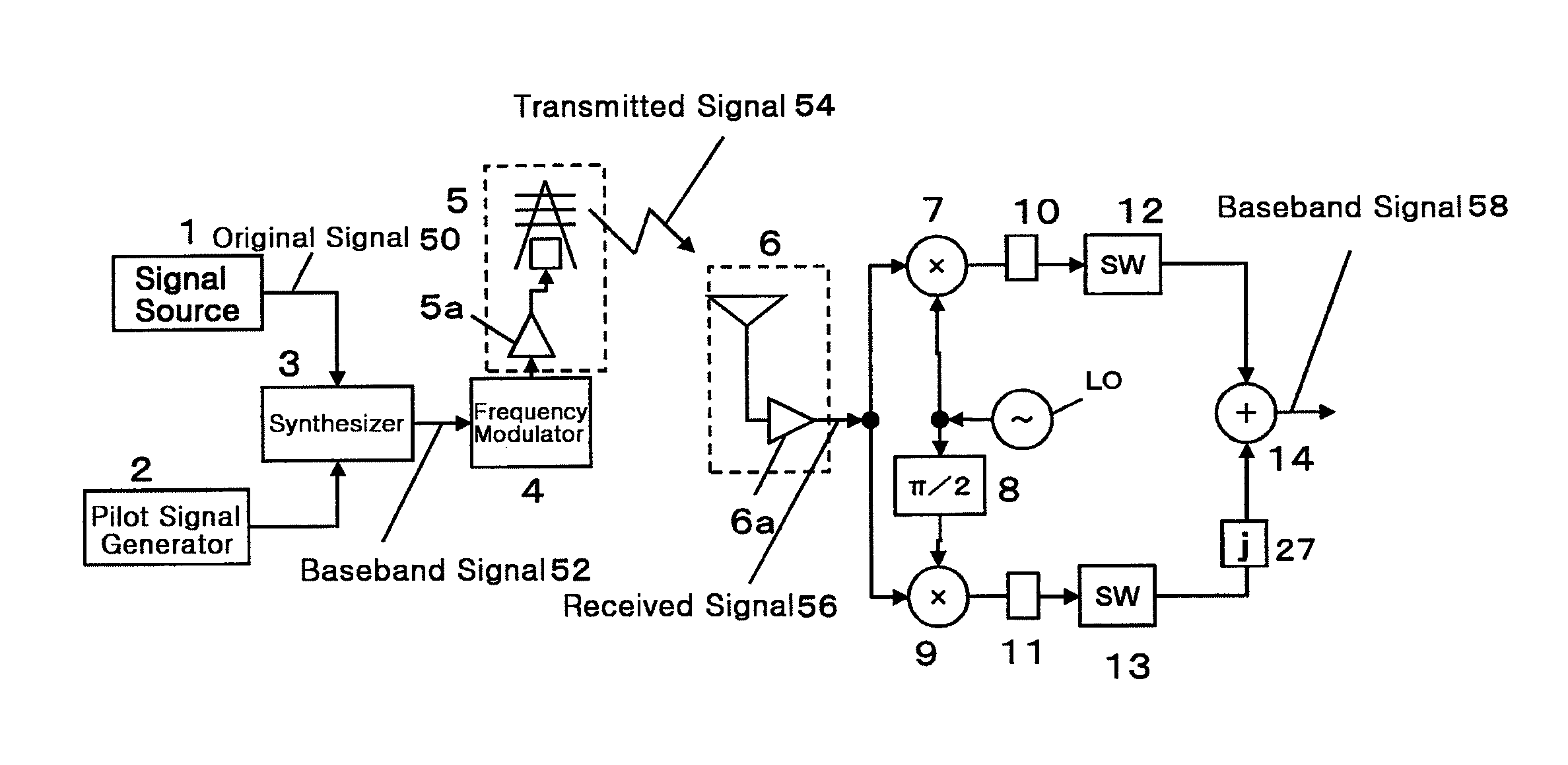
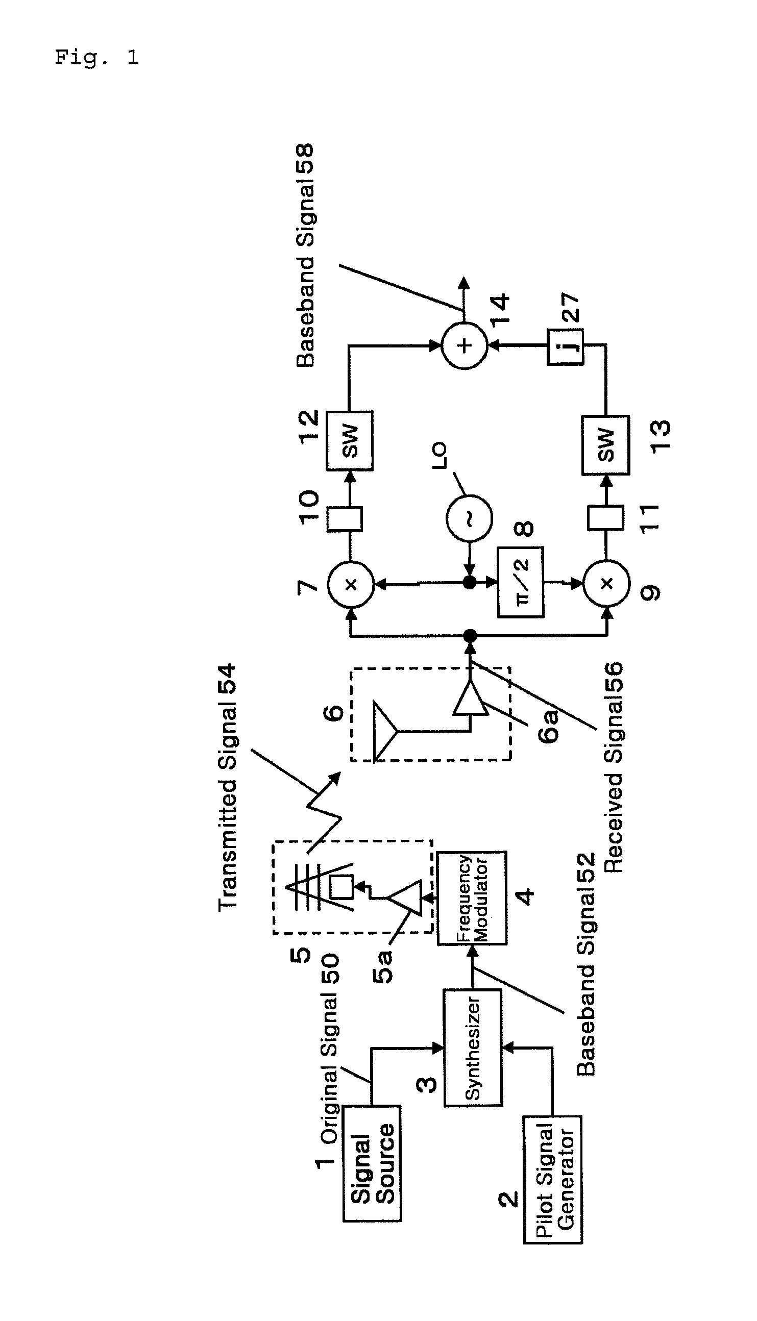
[0085]FIG. 1 is a schematic view of a transmit / receive system to be compensated according to the present invention. The descriptions below will be directed mainly to a case where the OFDM scheme is used. However...

second embodiment

[0202]FIG. 6 shows such an arrangement in which when the CFO is not zero, the receiver side RIQI and DCO, and the CFO are compensated for by disposing a delay filter on the I axis side and a (2L+1)-stage filter (matrix u) on the Q axis side. However, even when the compensations on the I axis and the Q axis are exchanged, the RIQI, DCO, and CFO can be compensated for.

[0203]FIG. 8 illustrates the configuration of the time domain compensation section 20 to perform that compensation method. The L-stage delay filter 23 is disposed on the Q axis, and the (2L+1)-stage filter u24 is disposed on the I axis. The constant λ is added from the Q axis signal to the I axis signal. In the first embodiment, the contents described in relationship to Equations (50) through (77) are exchanged between the I axis signal and the Q axis signal. However, since the Q axis signal is different in phase from the I axis signal and treated as the imaginary number, the I axis signal and the Q axis signal in the co...

example

[0221]The compensation method of the present invention was simulated to check the effects thereof. The OFDM system used for the simulation is similar to one in accordance with IEEE 802.11a WLAN, employing a carrier frequency of 5 GHz, B=20 MHz, N=64, and the 16 AQM signaling of NG1=16. The frequency selective fading channel has three paths and an exponential attenuating power profile.

[0222]The CFO is 100 kHz, and the I / Q imbalance scenario is to such that α=0.5 dB, φ=−10 degrees, β=1 dB, and ψ=5 degrees. Note that the other conditions were given as follows.

[Equation 114]

xI=[1, 0.1]T  (114)

[Equation 115]

xQ=[1, 0.2]T  (115)

[Equation 116]

yI=[1, −0.1]T  (116)

[Equation 117]

yQ=[1, 0.1]T  (117)

[0223]The transmitted distortion-free signal is normalized to 1, in the case of which the DCO power was set as follows.

[Equation 118]

|d|2ε[0,1]  (118)

Furthermore, the signal to noise ratio (SNR) was set to be 1 / σ2 with respect to the signal normalized to 1, while the noise variance was set to be σ2.

[...


PUM


Abstract

In a transmit / receive system, the carrier frequency offset (CFO), I / Q imbalance, and DC offset (DCO) can cause serious signal distortions. These analog losses can be compensated for individually or in combination of any two of them by following various methods that have been suggested. However, there have suggested no methods of simultaneously compensating, for these three types of losses that occur in actual devices at the same time. The present invention suggests a novel pilot signal that has a cyclic signal portion and a portion of two equally spaced continual signals. The invention provides a method for compensating for the CFO, I / Q imbalance, and DCO by simultaneously performing the time domain compensation and the channel estimation using those signal portions. The method also compensates for the I / Q imbalance and the channel response on the transmitter side in the OFDM scheme.

Description

TECHNICAL FIELD[0001]The present invention relates to a method for compensating for analog loss that occurs in the transmitter, the transmission line, and the receiver in a transmit / receive system that employs the OFDM scheme. More specifically, the invention relates to a method for collectively compensating for I / Q imbalance occurring in the complex modulator of a transmitter, the channel response and the carrier frequency offset in a transmission line, and the I / Q imbalance and the DC offset occurring in the complex modulator of a receiver.BACKGROUND ART[0002]Transmit / receive systems which employ the Orthogonal Frequency Division Multiplex (hereinafter referred to as the “OFDM”) in direct conversion transceivers suffer from degradation in transmission performance due to analog losses such as the carrier frequency offset, the transmitter / receiver I / Q imbalance, and the DC offset. Studies have been conducted on each of these loss factors separately.[0003]Note that throughout this sp...

Claims


Application Information

Patent Timeline
IPC IPC(8): H04B17/00H04L27/01
CPCH04B7/0426H04B7/0851H04B7/0854
Inventor LIN, HAIYAMASHITA, KATSUMI
Owner OSAKA PREFECTURE UNIV PUBLIC CORP
Why Eureka
Try Eureka