High speed operation method for Twin MONOS metal bit array
a metal bit array and high-speed operation technology, applied in the field of nonvolatile memory cells with twin monos structure, can solve the problem of area penalty of stitching area, and achieve the effect of saving memory cell area, and eliminating the set up time for the control gate voltag
- Summary
- Abstract
- Description
- Claims
- Application Information
AI Technical Summary
Benefits of technology
Problems solved by technology
Method used
Image
Examples
first embodiment
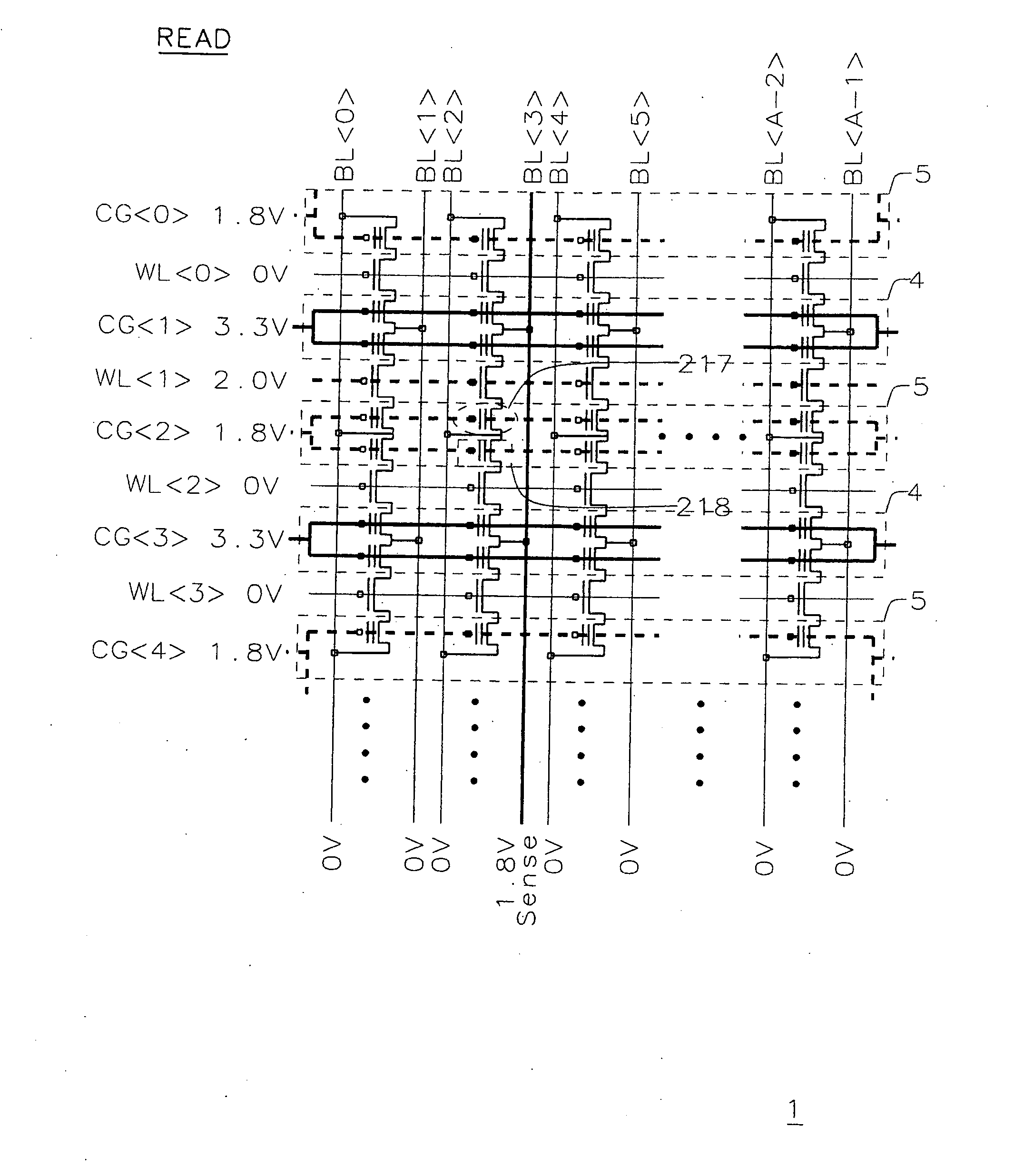
[0040]In the present invention, FIG. 15 shows the read operation voltage condition in a twin MONOS memory array 1. The selected cell 217 is supposed to be read. The cell 218 under the selected control gate CG2> is not selected. In FIG. 15, the even numbered control gates are set at the select voltage 1.8V and the odd numbered control gates are set at the override voltage 3.3V at the beginning of the read mode. The assembly of the cells under the even numbered control gate can be thought of as virtual “even bank”5. The assembly of the cells under the odd numbered control gate can be thought of as virtual “odd bank”4. The selected bit line BL3> is precharged at 1.8V before the selected word gate WL1> is turned on. The unselected bit lines are set at 0V. After the selected bit line BL3> is precharged at 1.8V, the selected word gate WL1> is set at 2V. The unselected WL's are set at 0V. The voltage level of the selected Bit line BL3> is detected by a sense amplifier after the selected wo...
second embodiment
[0049]Though the high enough override CG voltage is used for override in the prior art shown in FIG. 18, another override method is used in the present invention shown in FIG. 19A. In the present invention, 2.5V is applied to both CGs 23 and 25. That is, override voltage for the overrided cell 22 is eliminated. That is as if all the control gates were connected together as shown in FIG. 19B. However, the word gate 24 voltage can be applied independently of the control gate voltage. This condition is achieved electrically by applying the same voltage to all the control gates. The BL at the override side 26 is set at 1.5V (not precharge) and the BL at the select side 27 is set at 0V. After the CG voltage and BL voltage are set, WL is set at 2.0V. In the present invention, DIBL (Drain Induced Barrier Lowering) is utilized for override. Because the Vth of the override CG 23 is lowered enough by DIBL owing to the bit line voltage (1.5V), the read operation for the selected cell 21 can be...
third embodiment
[0057]FIGS. 24-27 show high-speed memory operation method using metal bit twin MONOS array where a pair of storage area regions hold complementary bits. Hereinafter, this method is called “complementary method”.
[0058]FIG. 24 shows the voltage condition of program operation in the complementary method where complementary memory cell 301 comprised of a pair of complementary bits is programmed. In the complementary method, one cell of the complementary memory cell 301 is programmed at data “0” and another one cell of the complementary memory cell 301 is programmed at data “1”. The programming of data “0” or inhibition of program (data “1”) is as described in the prior art of non-complementary method utilizing twin MONOS memory device.
[0059]To program data “0” in the left cell 310 and data “1” in the right cell 311, BL1> is set at 0V, BL2> is set at 4.5V and BL3> is set at 1.8V. 4.5V of BL2> is the BL program voltage and 1.8V of BL3> is program inhibit voltage. Select control gate CG2> ...
PUM
 Abstract
Description
Claims
Application Information
 - R&D
- Intellectual Property
- Life Sciences
- Materials
- Tech Scout
- Unparalleled Data Quality
- Higher Quality Content
- 60% Fewer Hallucinations
Browse by: Latest US Patents, China's latest patents, Technical Efficacy Thesaurus, Application Domain, Technology Topic, Popular Technical Reports.
© 2025 PatSnap. All rights reserved.Legal|Privacy policy|Modern Slavery Act Transparency Statement|Sitemap|About US| Contact US: help@patsnap.com


