
Energy storage systems

a technology of energy storage and energy storage devices, which is applied in the direction of domestic cooling devices, lighting and heating devices, machines/engines, etc., can solve the problems of excess wind power generated, diurnal variance in wind strength, and limited number of energy storage technologies availabl

Active Publication Date: 2011-08-25
PHASE CHANGE STORAGE
View PDF32 Cites 59 Cited by
  • Summary
  • Abstract
  • Description
  • Claims
  • Application Information

AI Technical Summary

Benefits of technology

The term “lower alkyl hydrocarbon” refers to a chemical compound with 6 or fewer carbon atoms, for example, 1, 2, 3, 4, 5 or 6 carbon atoms. The compound many also have one or more heteroatoms (e.g., O, N, S). The hydrocarbon can be branched or unbranched, and be saturated or unsaturated. The lower alkyl hydrocarbons for use

Problems solved by technology

Alternate energy systems such as solar photovoltaic (PV) and wind power face a challenge in that availability of energy supply is not synchronized with the demand for electricity.
At present, there are a limited number of technologies available to store energy at the scale required for utility-level consumption (i.e. on the order of several megawatts).
The challenge in utility operations is to balance the available supply with demand.
Wind power suffers from two deficiencies.
Furthermore, there is a diurnal variance in wind strength.
Unfortunately, there is an excess of wind power generated at night.
If the wind turbine operator generates power at night, they actually have to pay the utility.
The utility is willing to buy power during the day; however, there is less wind power availability (due to lower wind speeds) during the daylight hours.
In the former case, the transmission of power over the shared grid further contributes to grid instability.
Also, one wind turbine does not generate that much energy.
Furthermore, it is unclear if an organization could get such a civil engineering structure permitted today due to the alternation of the natural environment.
There are significant limitations to battery electrolyte chemistry.
The battery electrolyte must be electrically heated to greater than 300° C. The batteries have an implicit safety hazard due to the combination of high temperatures and the reactivity of molten sodium.
The systems are limited to locations with this resource.
Compressed air could be stored in pressure vessels; however, the storage density is low, thus many large and expensive pressure vessels would be required.
Furthermore, there is an inherent inefficiency in this storage mechanism.
The act of compressing air results in the creation of heat.
This is irreversible work and is a permanent loss of the system.
These systems have a significant challenge in that the flywheels require exotic composite materials.
The systems are capital intensive to scale up to the MW-hr range required for utility level power storage.
Unfortunately, this technique is not suitable for use with underground storage.
Hydrogen creation has all the same disadvantages of CAS with the added disadvantage that expensive, above-ground high pressure vessels are required to store the gas.
At present, state of the art units from Maxwell Technologies are more expensive than batteries when evaluated for their storage potential (A-hr).
This system does not generate electrical power.
This form of energy storage does not enable the energy that is stored in the ice to be recovered as electric current.

Method used


Image

  • Energy storage systems
  • Energy storage systems
  • Energy storage systems

Examples


Embodiment Construction

1. Introduction

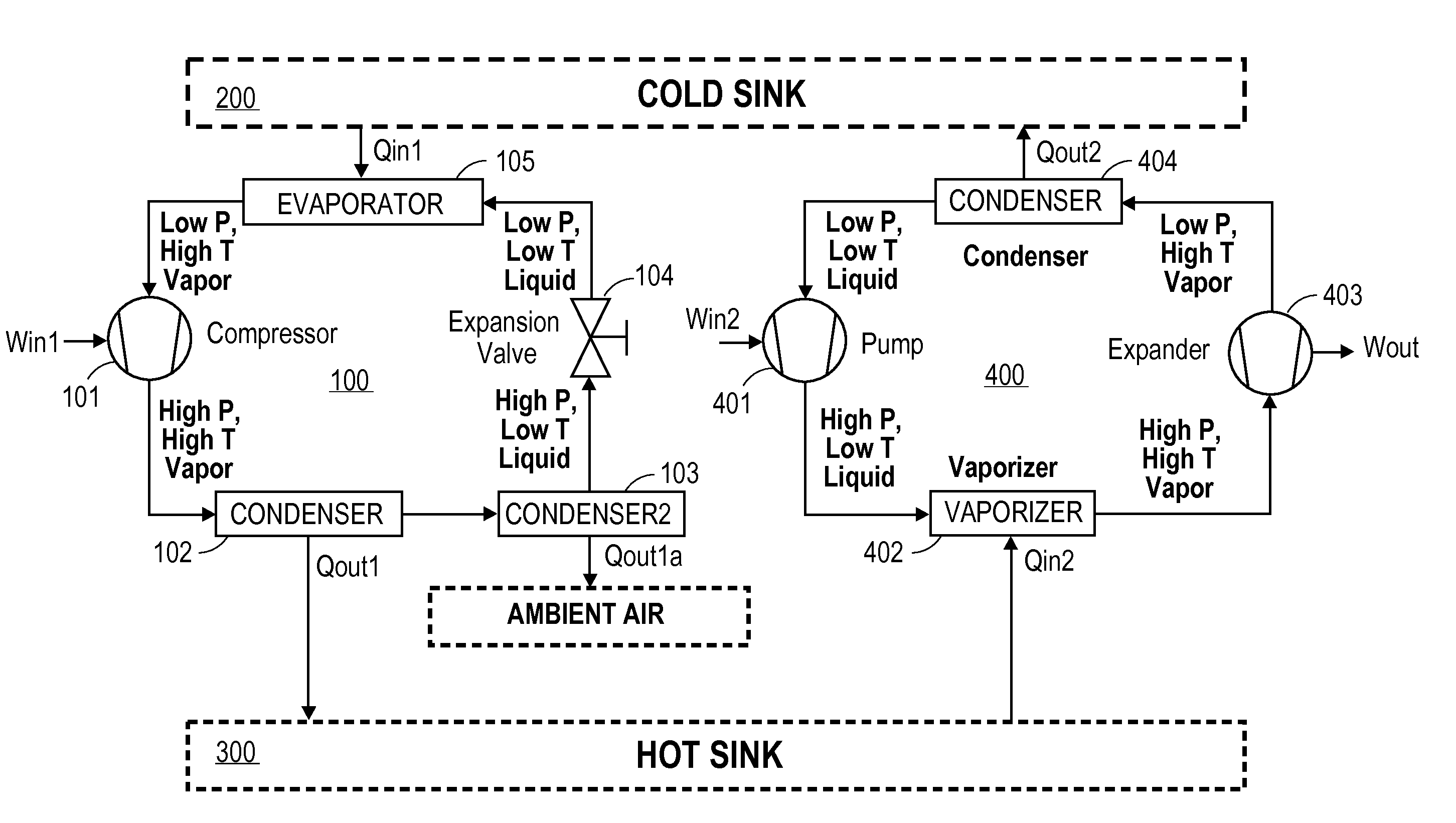
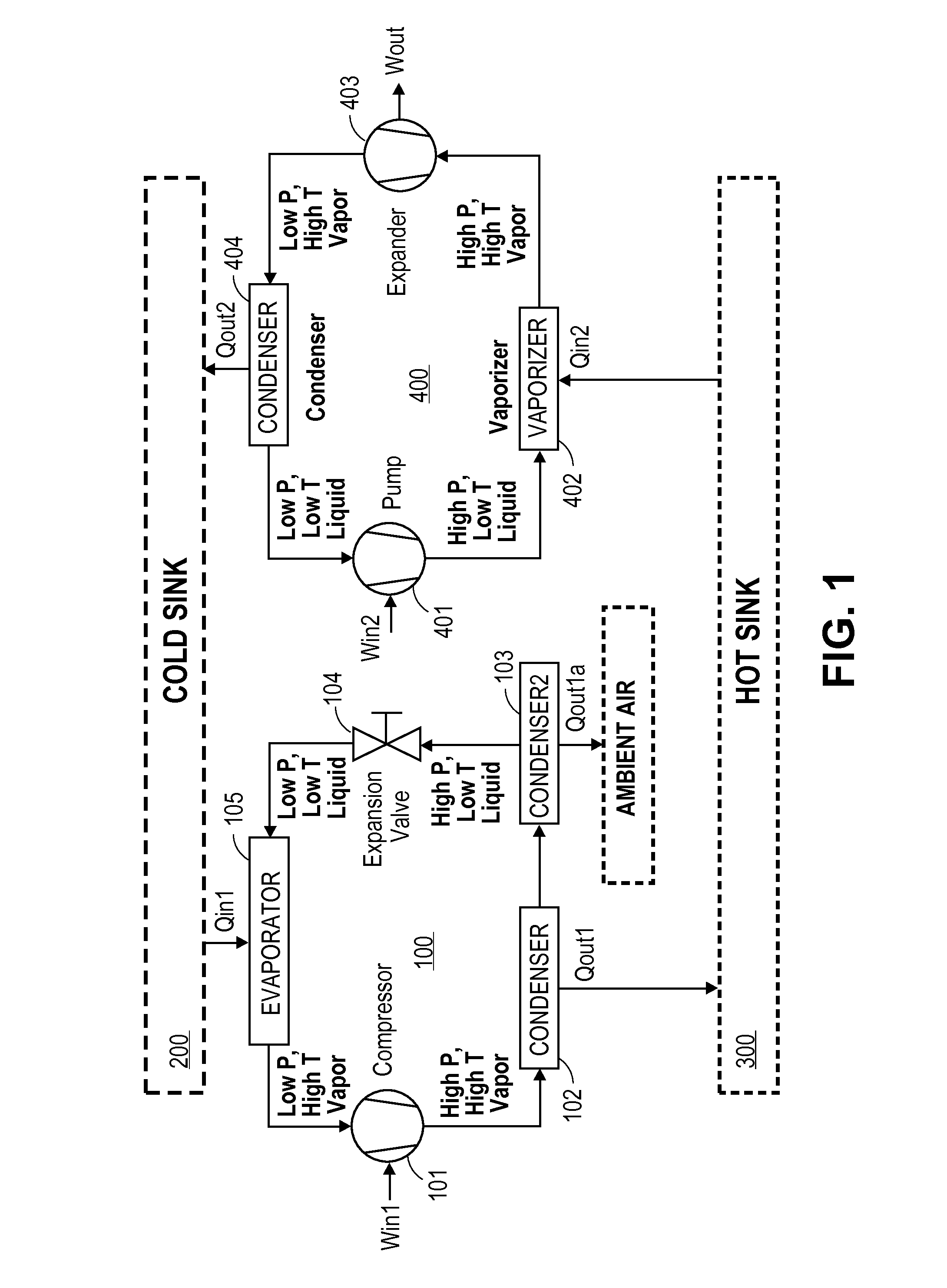
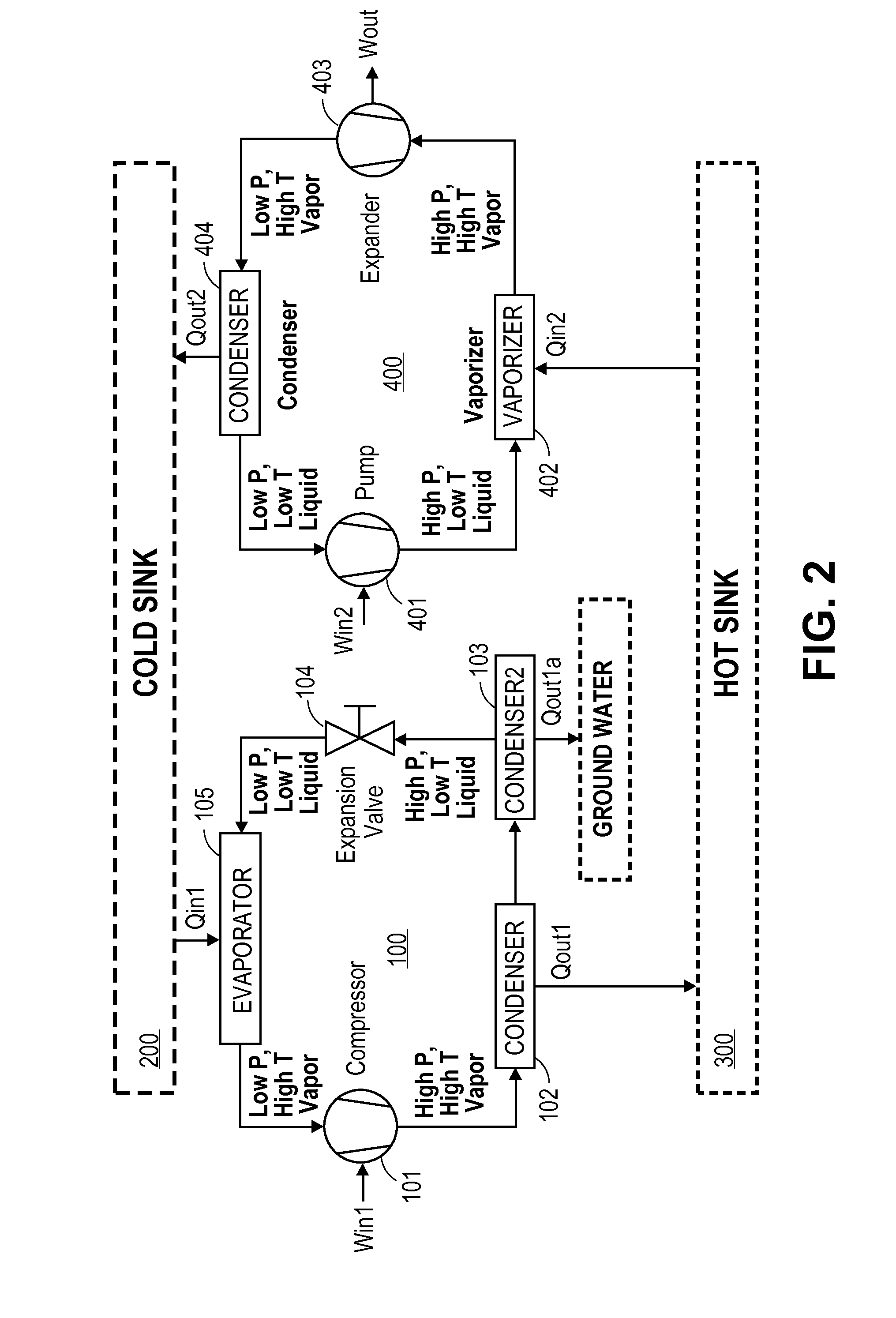
The present invention leverages the phase change in a phase change material to store thermal energy. Power from an alternate energy source is used to drive a refrigerant circuit to produce phase change in a cold sink and / or a hot sink. In various embodiments, the present energy storage systems utilize a hot source and a cold source that both employ phase change materials (PCM). The PCM assures that the hot and cold sources remain at constant temperature. Thus, the temperature difference for the storage circuit and generation circuit is constant. With the storage circuit, the input of electric power creates both cold and heat. The present energy storage systems utilize the storage energy in both the cold PCM and hot PCM. In certain embodiments, water or water in admixture with one or more salts finds use as a cold PCM. The generation circuits in the present energy storage systems offer increased efficiency because the hot and cold source is held at a nearly constant an...


PUM


Abstract

The present invention provides an energy storage device that utilizes a cold sink that undergoes cycles of freezing and thawing. The device converts electrical energy to stored thermal energy, and then re-converts the stored thermal energy to electrical energy, as needed or desired. The device can store energy on a large scale (e.g., on the order of megawatts or greater) and for an extended period of time (e.g., for at least 12 hours, or longer, as needed).

Description

FIELD OF THE INVENTIONThe present invention provides an energy storage device that utilizes a cold sink that undergoes cycles of phase change, e.g., freezing and thawing. The device converts electrical energy to stored thermal energy, and then re-converts the stored thermal energy to electrical energy, as needed or desired. The device can store energy on a large scale (e.g., on the order of megawatts or greater) and for an extended period of time (e.g., for at least 12 hours, or longer, as needed).BACKGROUND OF THE INVENTIONAlternate energy systems such as solar photovoltaic (PV) and wind power face a challenge in that availability of energy supply is not synchronized with the demand for electricity. At present, there are a limited number of technologies available to store energy at the scale required for utility-level consumption (i.e. on the order of several megawatts). The current US electrical grid can tolerate approximately 10% alternate energy supply. The challenge in utility ...

Claims


Application Information

Patent Timeline
IPC IPC(8): H02K7/18F25D11/00F25D3/12
CPCF25B6/04F25B25/005F25B27/00F01K25/10F25B2400/24F01K3/12F01K9/003F25B2339/047
Inventor WAIBEL, BRIAN J.
Owner PHASE CHANGE STORAGE
Learn More