Interfacing an inlet to a capillary channel of a microfluidic system

a microfluidic system and capillary channel technology, applied in the field of microfluidic systems, can solve the problems of incompatibility with the scale of the microfluidic analytical device, and achieve the effects of enhancing the wettability of the part, reducing the cross-section, and increasing the hydraulic resistance of the second passag

Inactive Publication Date: 2011-08-25
KONINKLIJKE PHILIPS ELECTRONICS NV
View PDF8 Cites 12 Cited by
  • Summary
  • Abstract
  • Description
  • Claims
  • Application Information

AI Technical Summary

Benefits of technology

[0045]In one embodiment, a filter material separates a first passage from the entrance of the capillary channel. Thus, at least a part of the second passage runs through the filter material. That is, a part of the second passage distinct from the first passage is formed by a filter material. The filter material reduces the cross-section of said part of the second passage. Furthermore, a filter material may enhance the wettability of said part of the second passage. For example, the filter material may be arranged to transport a fluid by wetting in the direction of the entrance of the capillary channel. For example, a first part of the reservoir may form the first passage, and the second part of the reservoir may contain the filter material and may form a part of the second passage, which is upstream of the common part of the first and second passages. Filter material may also be present in the first passage, in particular, in the common part of the first and second passages. The filter material may be formed integral with walls of the reservoir.
[0046]For example, the filter material separating the first passage from the entrance of the capillary channel increases the hydraulic resistance of the second passage. For example, the absence of filter material in a part of the first passage downstream of the common part of the first and second passages may render the hydraulic resistance of the first passage sufficiently low in order to effect said pressure reduction at the entrance of the capillary channel. Moreover, a filter material separating the first passage from the entrance of the capillary channel may prevent bubbles contained in the fluid from reaching the entrance of the capillary channel.
[0047]In one embodiment, the first passage is passable by bubbles contained in the fluid. Thus, air bubbles present in the fluid may be removed through the outlet. This facilitates the supply of fluid to the capillary channel.

Problems solved by technology

For example, when using a microfluidic analytical device, typically, samples are first acquired in volumes, which are far greater than, and incompatible with, the scale of the microfluidic analytical device.

Method used


Image

  • Interfacing an inlet to a capillary channel of a microfluidic system
  • Interfacing an inlet to a capillary channel of a microfluidic system
  • Interfacing an inlet to a capillary channel of a microfluidic system

Examples


Embodiment Construction

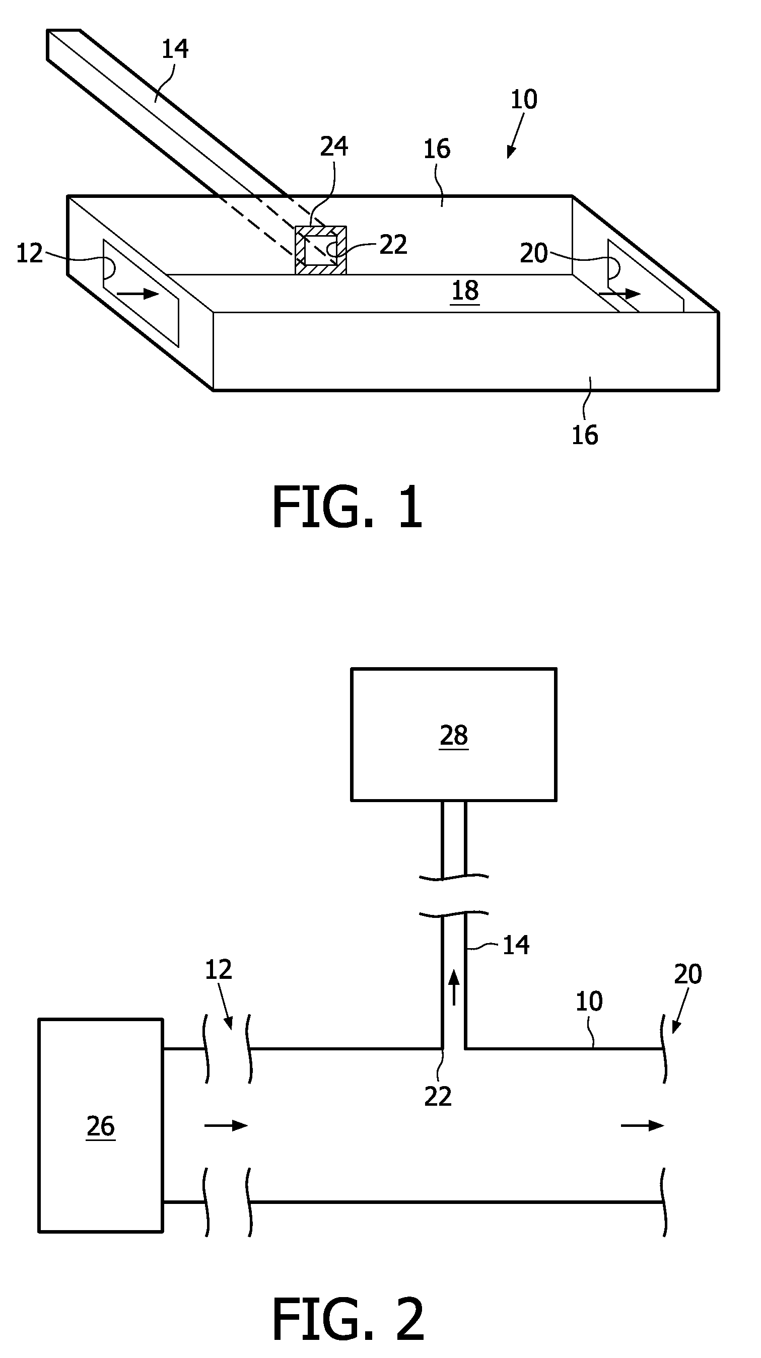
[0069]In FIG. 1, the geometrical construction of a reservoir 10 interfacing an inlet 12 to a capillary channel 14 of a microfluidic system is illustrated schematically. The reservoir 10 has a rectangular cross-section with sidewalls 16 and top and bottom walls 18. In FIG. 1, the top wall is not shown for illustrative purposes.

[0070]The inlet 12 is arranged in a front wall of the reservoir 10. An outlet 20 is arranged in a back wall of the reservoir 10. For example, the inlet 12 and the outlet 20 have respective cross-sections, which are smaller than the cross-section of the reservoir 10. The inlet 12, for example is connected to a front-end module for sample fluid capture or purification. The sample fluid is received by the reservoir 10 at the inlet 12 and begins to fill the reservoir 10.

[0071]In one sidewall 16, an entrance 22 of the capillary channel 14 is arranged. The inner walls 16, 18 of the reservoir 10, including an area 24 surrounding the entrance 22, have a substantially u...


PUM

PropertyMeasurementUnit
hydraulic resistanceaaaaaaaaaa
pressureaaaaaaaaaa
capillary forceaaaaaaaaaa

Abstract

The invention relates to microfluidic systems, and more specifically to a microfluidic system comprising a capillary channel (14) and an inlet (12) for receiving a fluid, as well as a method of filling a capillary channel (14). Provided is a microfluidic system, having an inlet (12) for receiving a fluid, a capillary channel (14), an outlet (20) for letting excess fluid out, and a reservoir (10) for interfacing the inlet (12) to the capillary channel (14). The reservoir (10) forms a first passage from the inlet (12) to the outlet (20), and a second passage from the inlet (12) to an entrance (22) of the capillary channel (14). A hydraulic resistance of the first passage is sufficiently low in order to effect a pressure reduction at the entrance (22) of the capillary channel (14) when a fluid is received under pressure at the inlet (12).

Description

FIELD OF THE INVENTION[0001]The invention relates to the field of micro fluidic systems, and more specifically to a microfluidic system comprising a capillary channel and an inlet for receiving a fluid.BACKGROUND OF THE INVENTION[0002]Significant advancements in the fields of chemistry and technology have been made due to the use of microfluidic technology.[0003]The term “microfluidic” is generally used to refer to a system or device having channels and chambers that are fabricated with at least one cross-sectional dimension, such as a depth, a width, or a diameter, of less than a millimeter. For example, microfluidic channels and chambers form fluid channel networks that allow the transportation, mixing, separation and / or detection of very small quantities of materials. Microfluidic devices are particularly advantageous, because they make it possible to perform various measurements, such as chemical, optical, etc. measurements, with small sample sizes and in automatable high-throug...

Claims


Application Information

Patent Timeline
Patent Type & Authority Applications(United States)
IPC IPC(8): B65B3/04B01L3/00
CPCB01L3/502715B01L3/502746B01L2200/027B01L2200/0621B01L2400/0688B01L2300/0816B01L2300/0877B01L2400/0406B01L2400/0487B01L2300/0681
Inventor SCHOLTEN, MONICAMAAS, JOOST HUBERTVERHOECKX, GODEFRIDUS JOHANNESVAN DER BEEK, MAURICE HUBERT ELISABETH
Owner KONINKLIJKE PHILIPS ELECTRONICS NV
Why Eureka
Try Eureka