
Bias charge roller comprising overcoat layer

a charge roller and overcoat technology, applied in the direction of corona discharge, non-metal conductors, instruments, etc., can solve the problems of inordinate maintenance of corotron wires, low charging efficiency, need for erase lamps and lamp shields, etc., to reduce streaking and increase service life

Active Publication Date: 2011-08-18
XEROX CORP
View PDF9 Cites 9 Cited by
  • Summary
  • Abstract
  • Description
  • Claims
  • Application Information

AI Technical Summary

Benefits of technology

The patent text describes a new type of bias charge roller for an image forming apparatus that reduces streaking and increases the lifespan of the roller. The roller has an overcoat layer made of a phenolic resin and a conductive agent, such as carbon black or metal oxide particles. The phenolic resin may be selected from a variety of options, such as formaldehyde polymers. The overcoat layer has a thickness of 1 μm to 15 μm. The apparatus also includes a power interface for supplying a voltage to the bias charge roller. The use of the new bias charge roller results in improved image quality and reduced streaking.

Problems solved by technology

Several problems have historically been associated with corona generating devices.
Problems include the use of very high voltages, i.e. from 3,000 to 8,000 V, requiring the use of special insulation, inordinate maintenance of corotron wires, low charging efficiency, the need for erase lamps and lamp shields, arcing caused by non-uniformities between the coronode and the surface being charged, vibration and sagging of corona generating wires, contamination of corona wires, and, in general, inconsistent charging performance due to the effects of humidity and airborne chemical contaminants on the corona generating device.
Perhaps the most significant problem with corona generating devices is the generation of ozone and nitrogen oxides.
Ozone poses well-documented health and environmental hazards.
Nitrogen oxides oxidize various machine components, adversely affecting the quality of the final output print produced.
Materials with resistivities which are too low will cause shorting and / or unacceptably high current flow to the imaging member.
Materials with too high resistivities will require unacceptably high voltages.
Other problems which can result if the resistivity is not within the required range include nonconformance at the contact nip and poor toner releasing properties.
These adverse effects can also result in the bias charge roller having non-uniform resistivity across the length of the contact member.
Other problems include resistivity that is susceptible to changes in temperature, relative humidity, and running time.
Bias charge rollers also cause wear and tear to imaging members because they physically contact the imaging member.
One of the more common problems is the appearance of streaks along the process direction, i.e. the circumference, or white and dark spots associated with surface damage.
These streaks may result in print defects that can shorten the lifetime of the bias charge roller, the imaging member, and the ink or toner cartridge.

Method used


Image

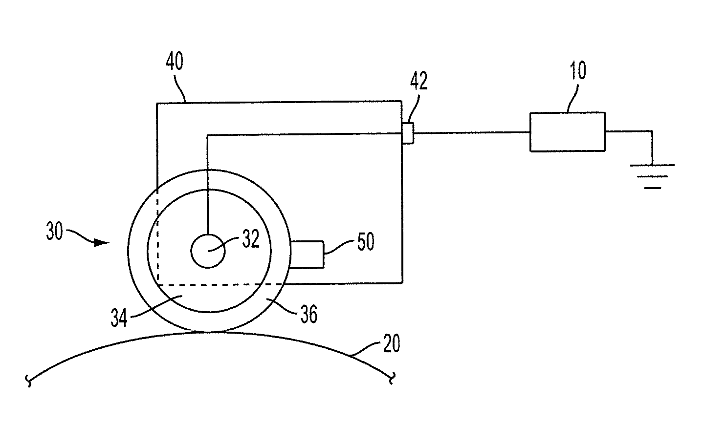
  • Bias charge roller comprising overcoat layer
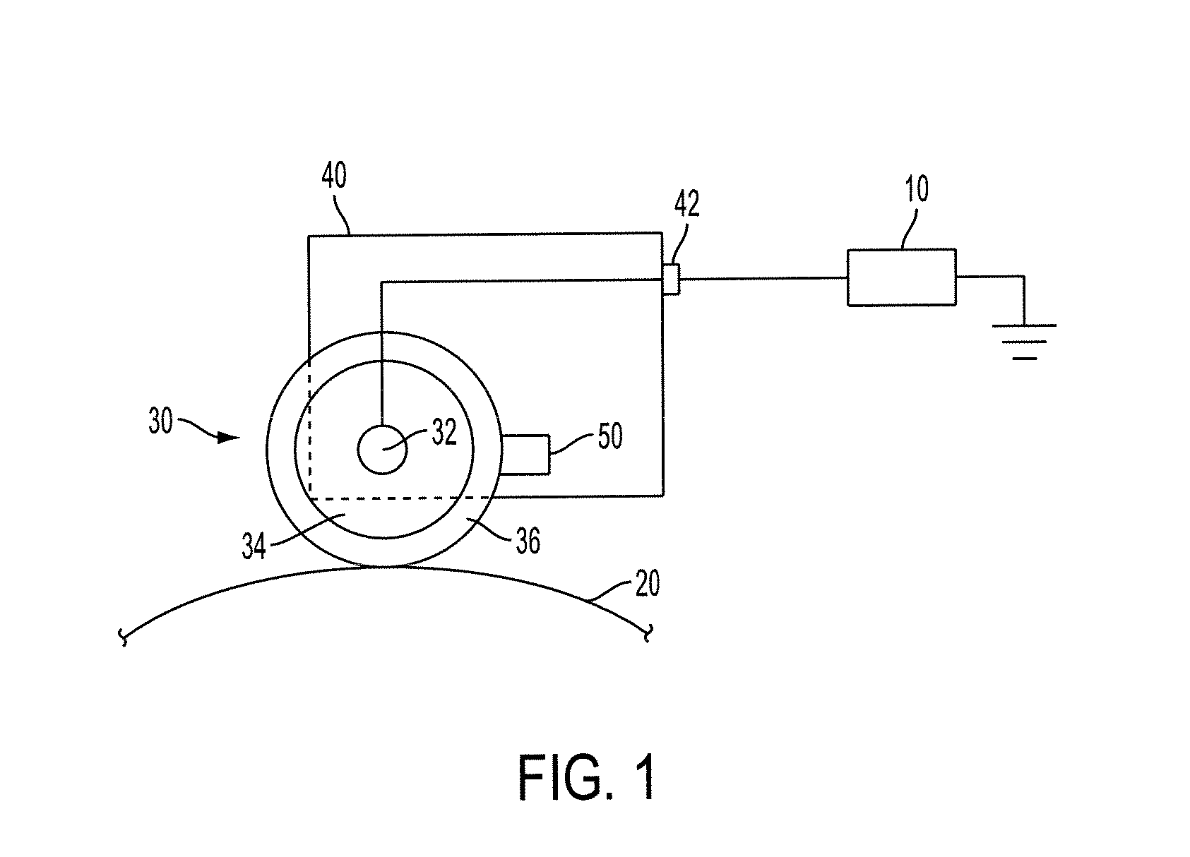
  • Bias charge roller comprising overcoat layer
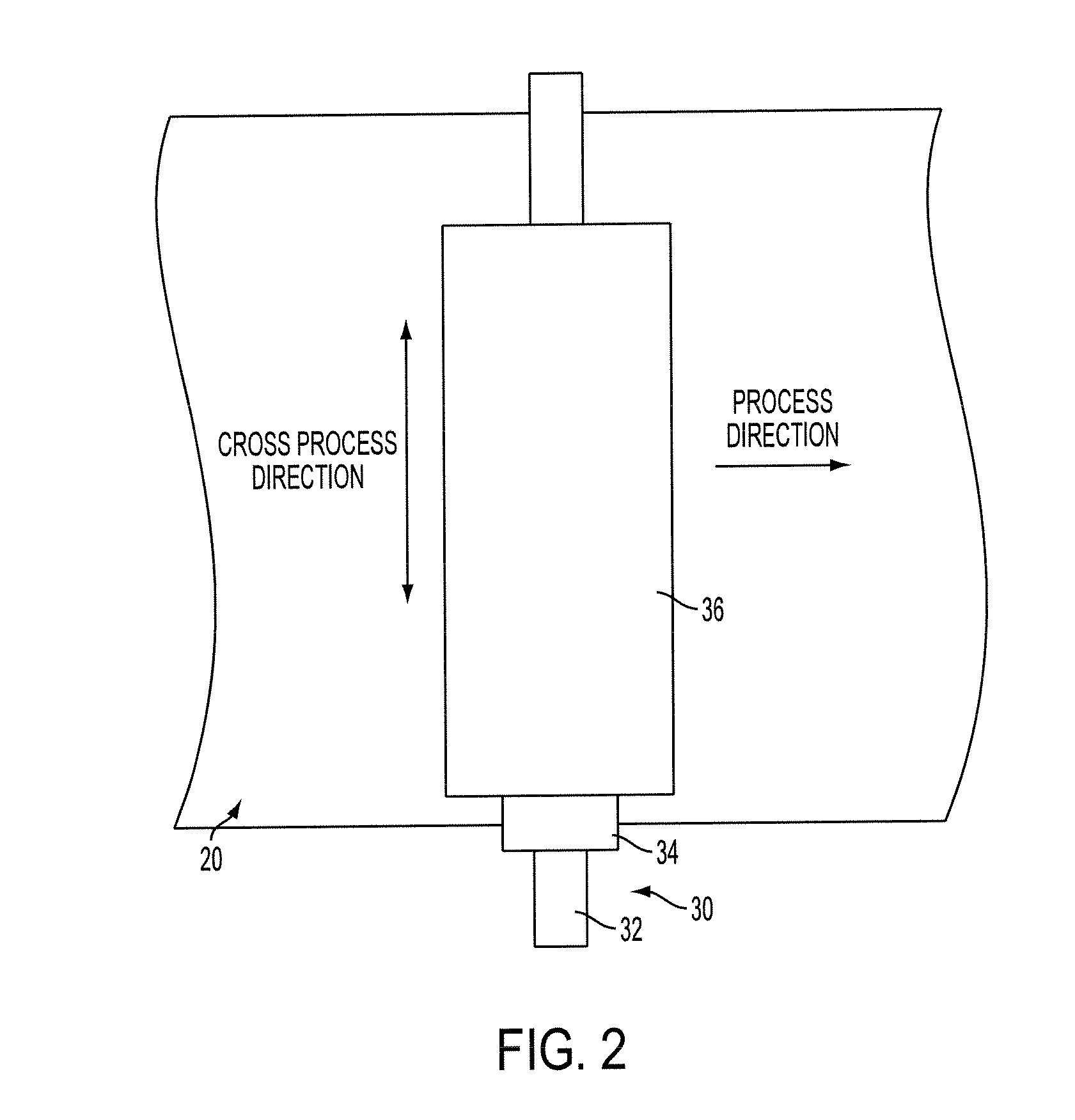
  • Bias charge roller comprising overcoat layer

Examples


example 1

[0052]An overcoat dispersion was prepared by ball milling a sample of Plyophen J-325 phenolic resin (available from Dainippon Ink and Chemicals, Inc.) with VULCAN® XC72 carbon black (available from Cabot Corporation) in a 50:50 mixture of xylene and butanol. The sample was ball milled for 3 days, after which the dispersion was filtered. A 5 μm overcoat layer was coated on a bias charge roller identical to the one used in Comparative Example 1 using a Tsukiage coater. The bias charge roller was then dried in a convection oven for 15 minutes at 140° C. to remove the solvent and cure the overcoat. The resulting overcoat layer was 5 wt % carbon black and 95 wt % phenolic resin. The surface resistivity of the material was measured to be 108 Ω / sq.

[0053]The bias charge roller was tested for charge uniformity prior to wear testing (t=0). The bias charge roller was then cycled 50,000 times in a Hodaka wear rate fixture, and subjected to charge uniformity testing using the same procedure (t=5...


PUM

PropertyMeasurementUnit
wt %aaaaaaaaaa
thicknessaaaaaaaaaa
wt %aaaaaaaaaa

Abstract

Disclosed are bias charge rollers having an overcoat layer. The overcoat layer comprises a phenolic resin and a conductive agent. The resulting bias charge rollers have reduced streaking and increased service lifetimes.

Description

BACKGROUND[0001]The present disclosure relates to overcoat layers useful in bias charge rollers, imaging apparatuses, and the rollers and apparatuses themselves. Among other advantages, the overcoat layers improve the lifetimes of the rollers and apparatuses while limiting streaking.[0002]Electrostatographic and xerographic reproductions may be initiated by depositing a uniform charge on an imaging member, i.e. photoreceptor, followed by exposing the imaging member to a light image of an original document. Exposing the charged imaging member to a light image causes discharge in areas corresponding to non-image areas of the original document while the charge is maintained on image areas, creating an electrostatic latent image of the original document on the imaging member. The latent image is subsequently developed into a visible image by depositing a charged developing material, i.e. toner, onto the photoconductive surface layer, such that the developing material is attracted to the...

Claims


Application Information

Patent Timeline
Patent Type & Authority Applications(United States)
IPC IPC(8): G03G15/02H01B1/12H01B1/24B32B27/42B32B27/04
CPCB32B27/42B32B2264/10B32B2307/302Y10T428/264G03G15/0233G03G2215/025B32B2429/02
Inventor GILMARTIN, BRIAN P.LIN, LIANG-BIHKOVAL, JEANNE M.STUCKEY, AARON M.
Owner XEROX CORP
Learn More