
Zipper for luggage and luggage using the same

Active Publication Date: 2011-08-18
C & C LUGGAGE MFG
View PDF13 Cites 8 Cited by
  • Summary
  • Abstract
  • Description
  • Claims
  • Application Information

AI Technical Summary

Benefits of technology

[0006]The present invention has been accomplished in view of the above-noted circumstances. It is therefore an objective of the present invention to provide a zipper for use in a luggage, which is simple in its construction and has less elements so as to simplify the process of making the luggage.
[0007]Another objective of the present invention is to provide a zipper for use in a luggage, which is durable in use.

Problems solved by technology

However, the correlative positions of the aforesaid three elements can hardly be maintained in a stable manner during the whole stitching work, resulting in that the fabric tape of the zipper may offset away from a predetermined rectilinear path where the tape is supposed to be located, which in turn results in that the slider can not move along the teeth smoothly, lowering the yield rate in production of the luggage.
In addition, the fabric tape stitched on the luggage will tend to be torn and then separated from the half shell after a long time of use due to the pull force acting thereon.

Method used


Image

  • Zipper for luggage and luggage using the same
  • Zipper for luggage and luggage using the same
  • Zipper for luggage and luggage using the same

Examples


Embodiment Construction

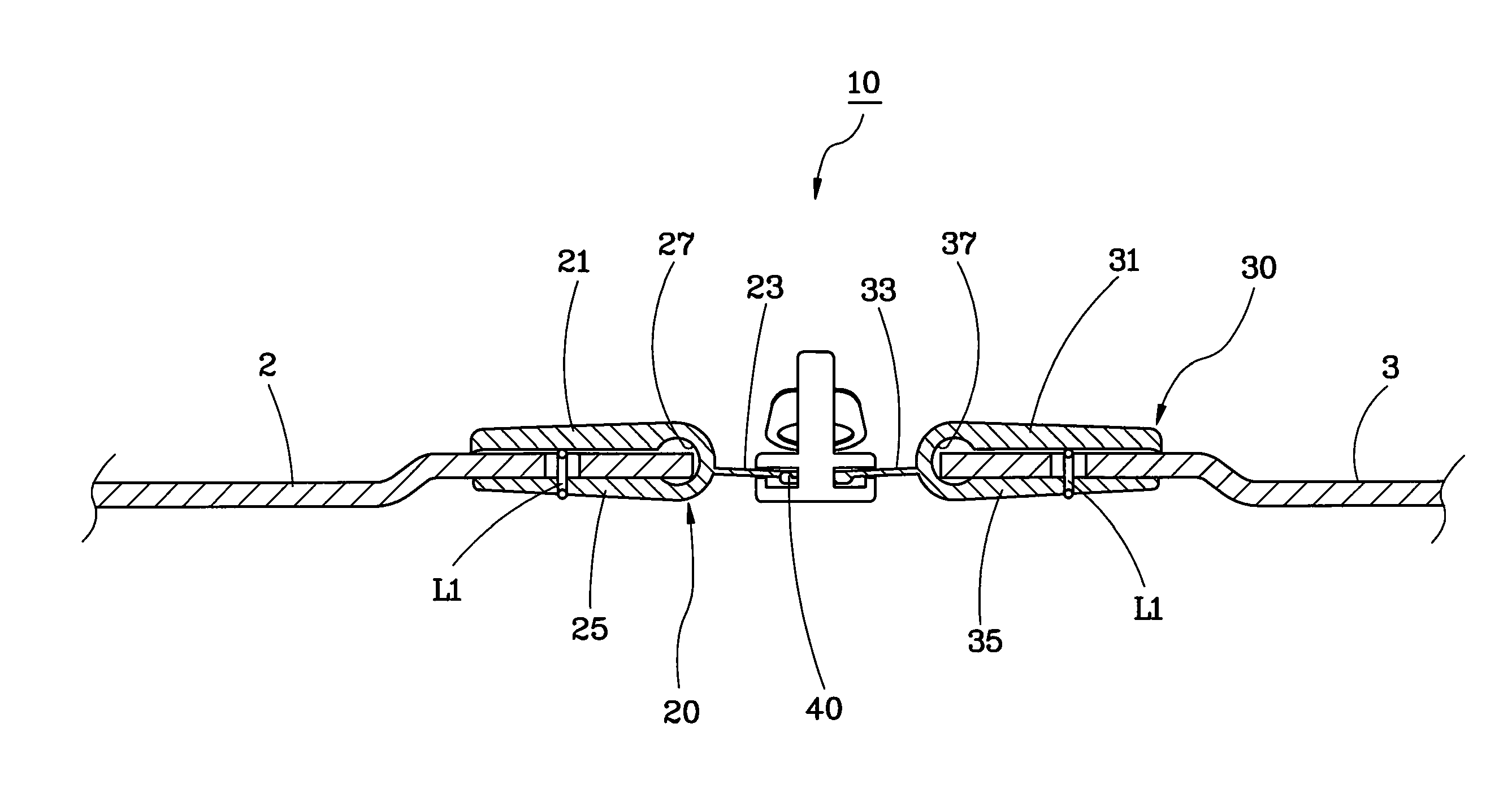
[0015]As shown in FIGS. 3 and 4, a zipper 10 provided according to a preferred embodiment of the present invention is used to be installed between a first half shell 2 and a second half shell 3. The zipper 10 comprises mainly a first tape 20, a second tape 30 and a plurality of interlockable teeth 40 arranged in two rows.

[0016]The first tape 20 is made of plastic material, such as polyvinyl (PVC), polypropylene (PP), polyethylene (PE), polycarbonate (PC), and the like. The first tape 20 has a shielding section 21, an extension section 23 and a mounting section 25, which are all integrally connected. An end of the shielding section 21 and an end of the mounting section 25 are integrally joined so as to jointly define a C-shaped restriction portion 27 therebetween. The extension section 23 extends outwardly from an outer surface of the joint where the shielding section 21 and the mounting section 25 are integrally connected to each other.

[0017]The structure and material of the second ...


PUM


Abstract

A zipper for a luggage includes a first tape, a second tape and interlockable teeth. The first tape has a shielding section for covering an end edge of a first half shell of the luggage, and a mounting section and an extension section connected with the shielding section respectively. The second tape has a shielding section for covering an end edge of a second half shell of the luggage, and a mounting section and an extension section connected with the shielding section of the second tape respectively. The teeth are mounted on the extension sections of the first and second tapes in two rows. By means of using the zipper in production of the luggage, the process of making the luggage can be simplified and the zipper can be well aligned with the half shells of the luggage, enhancing the yield rate in production of the luggage.

Description

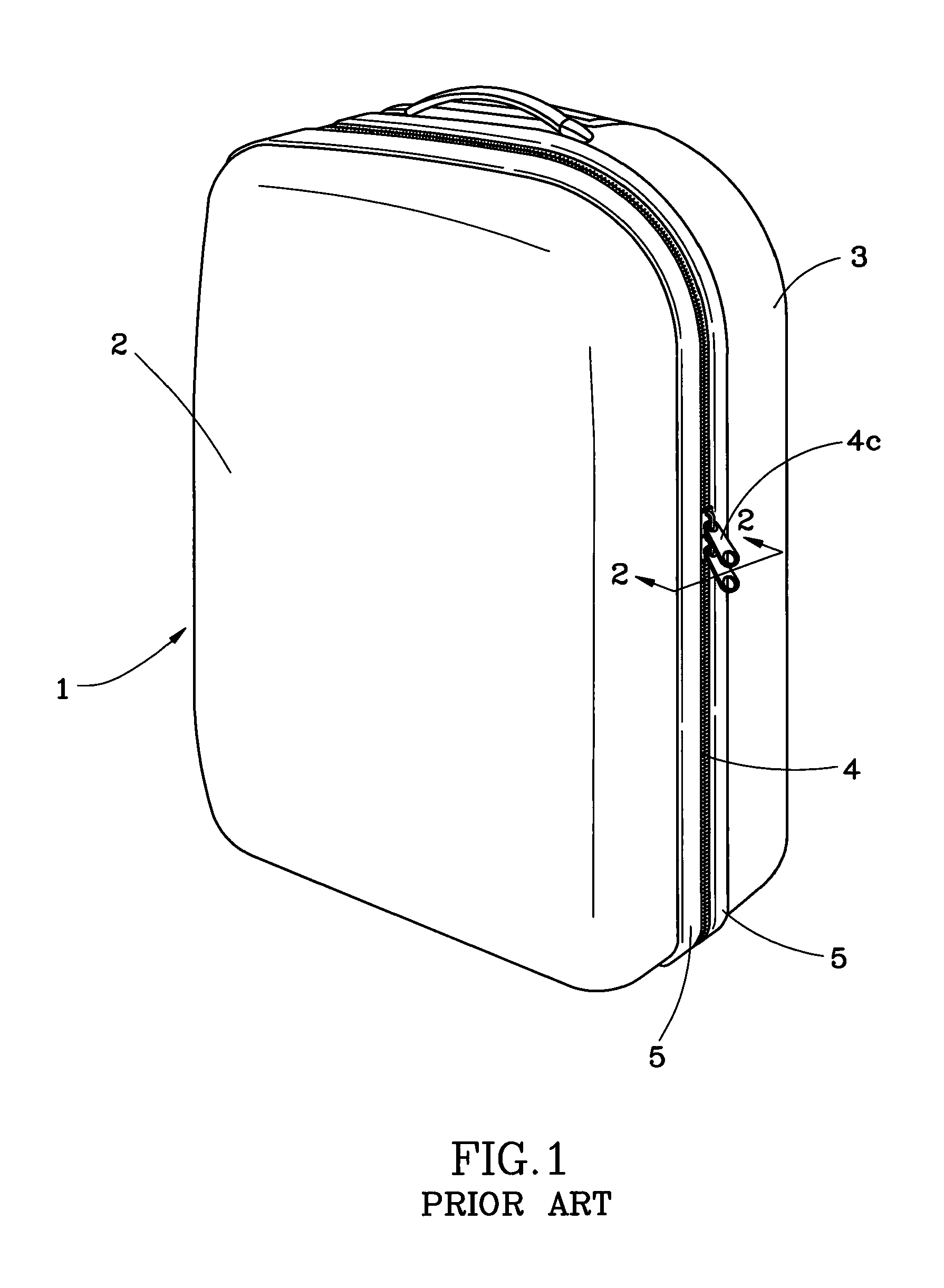
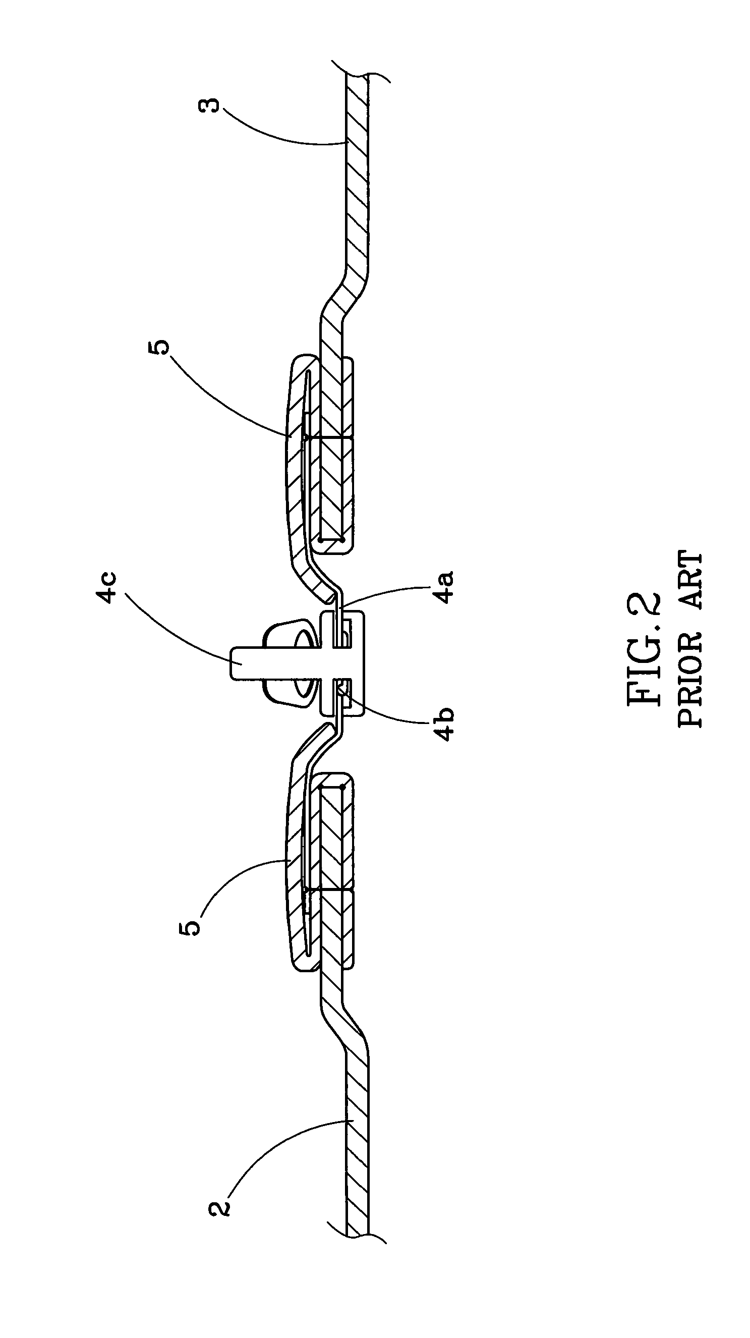
BACKGROUND OF THE INVENTION[0001]1. Field of the Invention[0002]The present invention relates generally to a zipper, and more specifically to a zipper for use in a luggage, and a luggage using the aforesaid zipper.[0003]2. Description of the Related Art[0004]FIG. 1 shows a perspective view of a luggage using a conventional zipper and FIG. 2 is a sectional view taken along line 2-2 of FIG. 1. As shown in FIGS. 1-2, the luggage 1 mainly comprises a first half shell 2, a second half shell 3, a zipper 4 installed between the first and second half shells 2 and 3 for joining the half shells 2 and 3, and two end strips 5 respectively mounted to the periphery edges of the first and second half shells 2 and 3 and connected with two fabric tapes 4a of the zipper 4 respectively. In addition to the fabric tapes 4a, the zipper 4 further includes a plurality of interlockable teeth 4b mounted on the two fabric tapes 4a in two rows and a slider 4c reciprocally moveable along the path defined by the...

Claims


Application Information

Patent Timeline
IPC IPC(8): A45C13/10A44B19/02A44B19/36
CPCA44B19/34A45C13/103Y10T24/25Y10T24/2598Y10S190/903
Inventor CHIANG, HSI-WU
Owner C & C LUGGAGE MFG
Learn More