
Underwater Breathing Apparatus

a breathing apparatus and underwater technology, applied in the direction of life-saving devices, inhalators, waterborne vessels, etc., can solve the problem of limited underwater time by the capacity of air tanks, and achieve the effect of reducing water leakag

Inactive Publication Date: 2011-08-18
ABULRASSOUL ABDULLAH M +1
View PDF29 Cites 10 Cited by
  • Summary
  • Abstract
  • Description
  • Claims
  • Application Information

AI Technical Summary

Benefits of technology

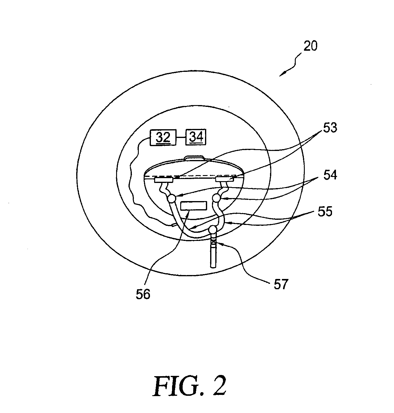
"The present invention is an underwater breathing apparatus that can provide breathable air to a user for an extended period of time. It includes a water resistant enclosure for floating on the surface of a body of water and an air collection header with an air pump for generating a constant flow of breathable air. The system also includes a check valve for exhausting air while eliminating leakage of water into the system. The apparatus also includes a safety flag for indicating the presence of an individual below the surface of the water, a safety warning light for use in darkness, and a fresh air tube that supplies air to the air pump and prevents water from entering into the water resistant enclosure. Additionally, the apparatus includes a retractable hose mechanism for automatically reeling out the air hose when a diver descends and reeling in the air hose when the diver ascends."

Problems solved by technology

However, there is extensive training required for such devices and the time underwater is limited by the capacity of the air tank.

Method used


Image

  • Underwater Breathing Apparatus
  • Underwater Breathing Apparatus
  • Underwater Breathing Apparatus

Examples


Embodiment Construction

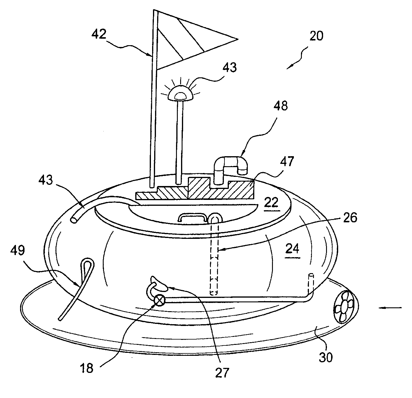
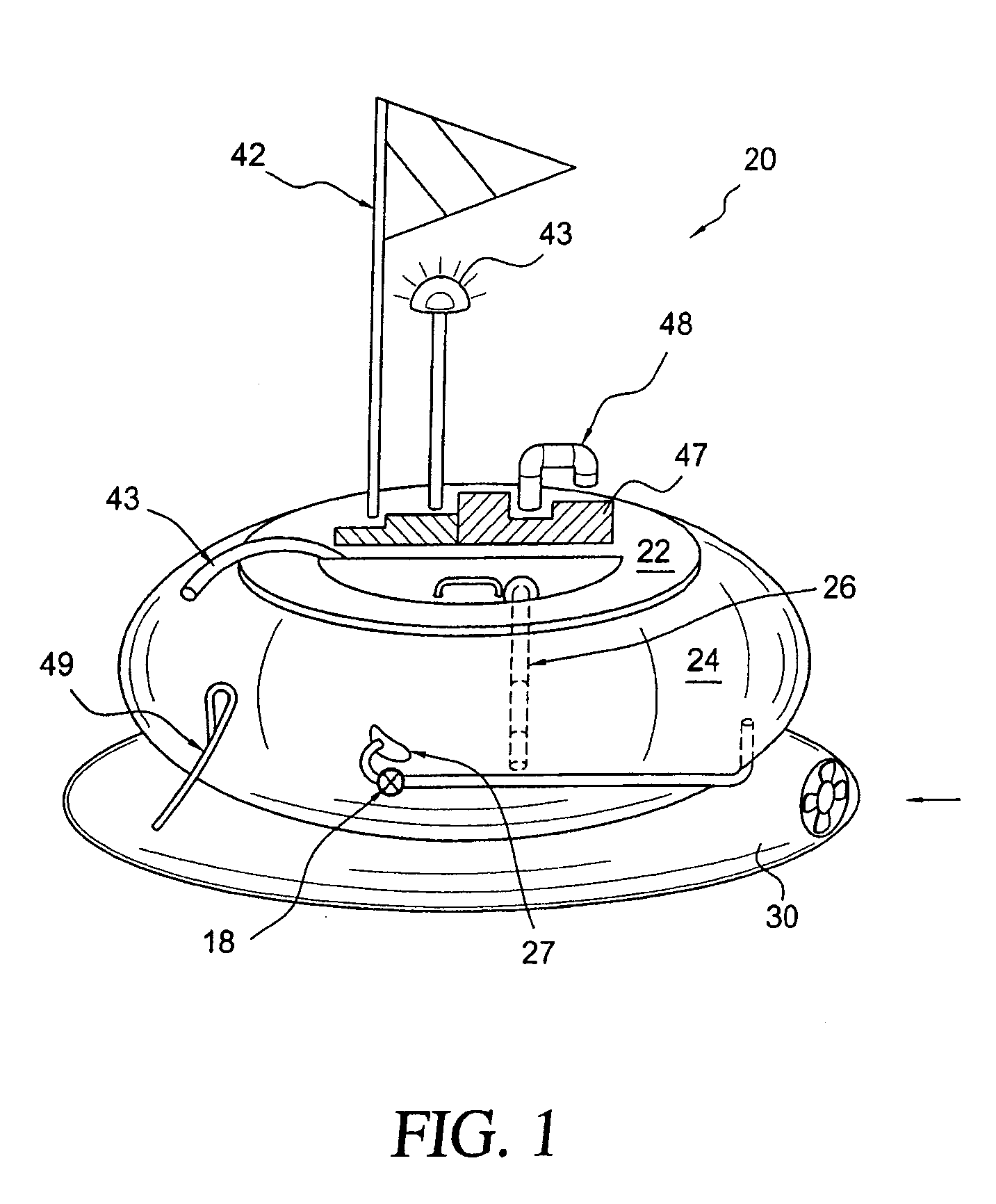
[0012]As illustrated in FIG. 1 an underwater breathing apparatus 20 in accordance with a preferred embodiment of the present invention includes a water resistant enclosure 22 that is floated on the surface of a body of water. The water resistant enclosure 20 can be made of any suitable plastic, as for example polyethylene, polypropylene, and polyvinylchloride or other weldable thermo plastic resin. The construction and dimensions are such as to accommodate a flotation device 24 as for example a rubber inner tube to support the water resistant enclosure 22.

[0013]The flotation device 24 is inflated with air in a conventional manner and is secured to the water resistant enclosure 22 by conventional means and as illustrated surrounds the water resistant enclosure 22. An air supply line runs from the water resistant enclosure 22 to the one or more users (not shown) mouth pieces 27. An important aspect of the invention resides in a small jet ski 30 that is used by a diver in the event tha...


PUM


Abstract

An underwater breathing apparatus includes a water resistant enclosure for floating on the surface of a body of water. An air collection header and an air pump for generating a constant flow of breathable air, an air supply line for delivering a flow of the breathable air to a user and a check valve for exhausting used air are also provided. At least one mouth piece connected to one of said supply lines and to a user's mouth together with a solar powered rechargeable battery connected to the air pumps enables the air pump to supply breathable air to the user. A safety flag mounted on the water resistant enclosure and extending upward therefrom indicate the presence of an individual below the surface of the water as does a safety warning light mounted on top of the water resistant enclosure. A fresh air vent tube supplies air to the air pump and prevents water from entering the water resistant enclosure while a jet ski fixed to an underside of said water resistant enclosure and guided by the user is used for moving the water resistant enclosure to a different area. Finally, a tether line connects the user to the jet ski while a retractable hose mechanism automatically reels out air hoses when a diver descends and reels in the air hose when the diver ascends. In the preferred embodiment of the invention a micro-computer contains the data from dive tables and automatically reels in and stops at various steps the air hose.

Description

FIELD OF THE INVENTION[0001]This invention to an underwater breathing apparatus and more particularly to an underwater breathing apparatus that provides fresh breathable air to one or more divers.BACKGROUND FOR THE INVENTION[0002]Underwater breathing devices are well known and have been in use for many years. For example, breathing devices were disclosed by Jacque Cousteau in the 1950s (see Cousteau U.S. Pat. No. 2,953,988) that incorporates a pressurized tank of air worn by a diver on their back that lead to “SCUBA” gear (self contained underwater breathing apparatus). In such systems, the air pressure is regulated according to the demand and depth and is supplied to the diver through a hose or mouth piece. The diver can swim freely and breath at depths well below the surface with tank pressure significant to compensate for water pressure. However, there is extensive training required for such devices and the time underwater is limited by the capacity of the air tank.[0003]In an ef...

Claims


Application Information

Patent Timeline
Patent Type & Authority Applications(United States)
IPC IPC(8): B63C11/14B63C11/02
CPCB63B35/73B63C11/26B63C11/202B63B2209/18B63B34/52
Inventor ABULRASSOUL, ABDULLAH M.QASEM, SADEG A.
Owner ABULRASSOUL ABDULLAH M
Learn More