
Method for compensating for volume changes of an hydraulic fluid in an hydraulic actuating device for actuating a clutch, and hydraulic actuating device

a technology of hydraulic actuating device and hydraulic fluid, which is applied in the direction of mechanical actuating clutch, mechanical equipment, instruments, etc., can solve the problems of deviation from the desired clutch torque or slip torque, and considerable disturbing effect on the nominal clutch characteristic curv

Inactive Publication Date: 2011-08-11
ROBERT BOSCH GMBH
View PDF34 Cites 2 Cited by
  • Summary
  • Abstract
  • Description
  • Claims
  • Application Information

AI Technical Summary

Benefits of technology

The present invention provides a method and clutch that can balance changes in volume caused by temperature fluctuations in hydraulic fluid. The method involves correcting the position of the piston of the master cylinder based on temperature, while the clutch uses temperature-dependent correction of the piston position to balance changes in the hydraulic fluid in the slave cylinder and the hydraulic line between the cylinders. The position of the piston is corrected by controlling the actuator based on the temperature difference between the measured temperature at the slave cylinder and a reference temperature. The position correction is particularly useful when the hydraulic fluid is heated or cooled quickly, such as when the clutch is opened or closed. The method and clutch can improve the performance and efficiency of hydraulic systems.

Problems solved by technology

A thermal expansion or contraction of this volume therefore leads directly to a change in the force exerted by the piston rod on the disk spring, and, via the latter, on the pressure force of the clutch disks, and consequently to deviations from the desired clutch torque or slip torque.
Since the hydraulic volume located in the slave cylinder, when the separating clutch is opened, makes up a large proportion of the total volume of the enclosed hydraulic fluid, a volume increase is possible in this case, which results in considerable disturbing effects on the nominal clutch characteristics curve, and, with that, deviations in the desired clutch torque or the slip torque.

Method used


Image

  • Method for compensating for volume changes of an hydraulic fluid in an hydraulic actuating device for actuating a clutch, and hydraulic actuating device
  • Method for compensating for volume changes of an hydraulic fluid in an hydraulic actuating device for actuating a clutch, and hydraulic actuating device
  • Method for compensating for volume changes of an hydraulic fluid in an hydraulic actuating device for actuating a clutch, and hydraulic actuating device

Examples


Embodiment Construction

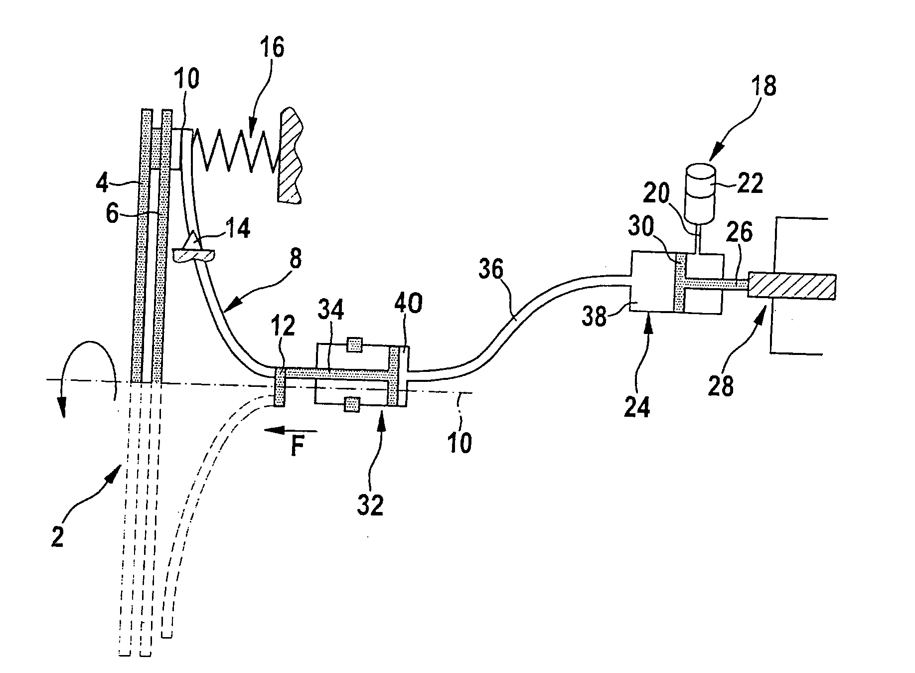
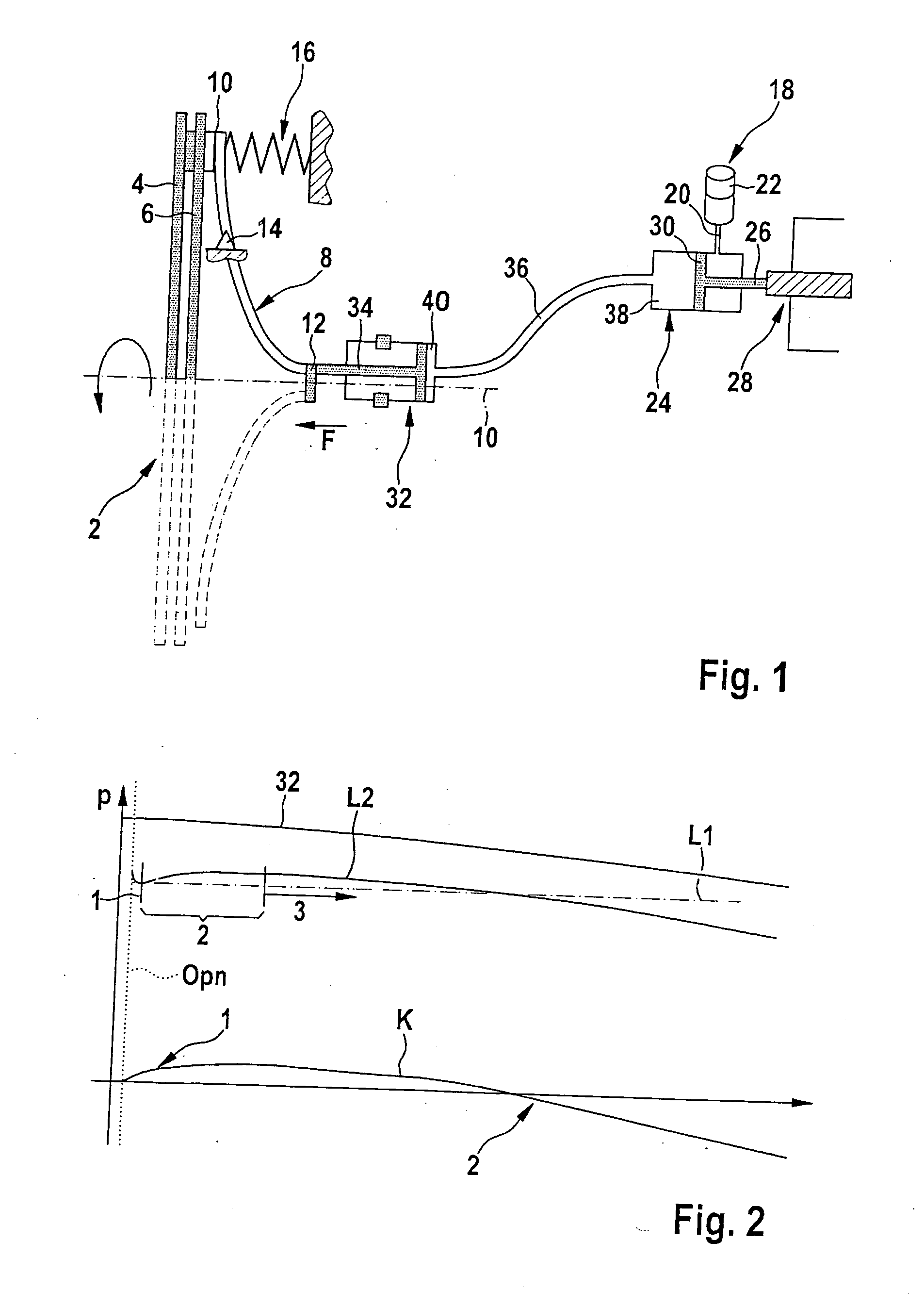
[0019]Separating clutch 2, shown in the drawing, of a non-power-splitting parallel hybrid drive of a motor vehicle is situated between an internal combustion engine of the hybrid drive and a drive train of the motor vehicle. Separating clutch 2 is used, on the one hand, to decouple the internal combustion engine from the drive train upon the transition to electrical driving operation, when the motor vehicle is to be operated only with the aid of an electric machine of the hybrid drive, and on the one hand, upon an increased power requirement and / or upon a low battery charge state, to start the internal combustion engine again for the transition into the hybrid driving operation, using the electric machine.

[0020]As is shown best in FIG. 1, separating clutch 2 includes two clutch disks 4, 6 and a bent disk spring 8, in the form of a flat funnel, which rotate in common about the rotational axis 10 of the crankshaft of the internal combustion engine. Disk spring 8 is connected at its ou...


PUM


Abstract

In a method for compensating for volume changes of a hydraulic fluid in an actuating device used for actuating a clutch, which actuating device includes a master cylinder, an actuator connected to a piston of the master cylinder, and a slave cylinder hydraulically connected to the master cylinder for disengaging the clutch. The position of the piston of the master cylinder is corrected as a function of temperature and that the actuating device include an element for the temperature-dependent correction of the position of the piston of the master cylinder.

Description

BACKGROUND OF THE INVENTION[0001]1. Field of the Invention[0002]The present invention relates to a method for compensating for volume changes of an hydraulic fluid in an hydraulic actuating device for actuating a clutch.[0003]2. Description of Related Art[0004]Hydraulically actuated clutches are used, among other things, as separating clutches between an internal combustion engine and the drive train of motor vehicle hybrid drives, in the form of non-power-splitting-parallel hybrids, in order to decouple the internal combustion engine from the drive train for the purely electrical vehicle operation by opening the separating clutch, or to start it again by closing the separating clutch in case of increased power demand or a low battery charge state, by using the electric machine.[0005]In order to avoid disturbances in the drive train, the separating clutch is controlled during the opening and the closing in such a way that a specified clutch torque or slip torque is present between i...

Claims


Application Information

Patent Timeline
Patent Type & Authority Applications(United States)
IPC IPC(8): F16D48/06F16D48/02
CPCF16D25/08F16D48/02F16D48/066F16D2500/1024F16D2500/50275F16D2500/3026F16D2500/30404F16D2500/3122F16D2500/1066F16D25/087F16D13/02F16D48/06
Inventor URBAN, WERNERKLYMENKO, MYKHAYLO
Owner ROBERT BOSCH GMBH
Learn More