Collimator with an adjustable focal length

a collimator and adjustable technology, applied in the direction of material analysis, material analysis using wave/particle radiation, instruments, etc., can solve the problems of high cost of monochromatic x-ray generation, inability to locate within the object to be examined, and high requirement for traveling units, so as to simplify the structure and operation of the x-ray inspection system

Active Publication Date: 2011-07-28
SMITHS HEIMANN
View PDF13 Cites 2 Cited by
  • Summary
  • Abstract
  • Description
  • Claims
  • Application Information

AI Technical Summary

Benefits of technology

[0010]It is therefore an object of the present invention to simplify the structure and operation of an x-ray inspection system based on the diffraction principle.
[0012]This type of collimator includes substantially an x-radiation-absorbing housing. Within the housing, there are at least two parallel diaphragms, each with at least one substantially circular slot about a common central axis. This central axis corresponds to the rotation axis of the desired cone-shaped passband of the collimator. It is possible to vary the aperture angle and thereby the focal length of the collimator by the parallel displacement of at least one diaphragm along this central axis. In a detector / collimator combination unmovable relative to object to be examined, this angle adjustment corresponds to an adjustment of the focus along the central axis and thereby to the selection of a desired point within the object to be examined. To increase the effectiveness of the collimator and thereby the entire inspection system, the diaphragms consist advantageously of highly radiation-absorbing material. This assures that substantially only the radiation striking at the set angle and passing through the slot reaches the detector disposed behind the collimator.
[0015]With the use of this type of x-ray examination device, an x-ray examination procedure can be performed in which the object to be examined is radiated with a pencil beam of broad-band x-radiation and diffraction spectra are taken for different diaphragm settings by means of the x-ray detector. In this case, first a focal length is set by positioning the diaphragms and thereby a specific point is focused. In this case, the collimator allows only the radiation to pass that is diffracted at the angle specified by the diaphragm setting at the focused point. Comparison of the received spectrum measured at the detector with the known spectrum of the emitted pencil beam can determine the energy at which diffraction at the set angle occurred. The atomic structure of the material at the focused point can be determined and the substances present there identified.
[0016]In an embodiment, there is the possibility that the taken spectra are compared with reference spectra. Thus, for example, reference spectra for known critical substances can be taken at different diaphragm settings and stored. Because a pencil beam with the same energy spectrum is used in measuring the reference spectra and the later inspection procedure, the critical substances can be easily identified by comparison of the received spectrum with the reference spectra.

Problems solved by technology

In addition, care must be taken that radiation diffracted only at a single point is detected, because otherwise localization within the object to be examined is not possible.
Because it is technically very costly to generate monochromatic x-radiation, the highly limited x-ray used for testing, the so-called pencil beam, has an energy spectrum known, for example, from measurements.
The disadvantage of this method is that, on the one hand, a highly precise traveling unit is required and, on the other, the entire device must have an overall height more than twice the height of the object to be examined.
The use of a non-segmented detector, which is not position-sensing and therefore provides a common output signal for all focused points, however, results in the disadvantage that the evaluation and clear assignment of the detected radiation to a diffraction point are difficult.
With use of a segmented detector, which, for example, is divided into separately evaluable circular rings, this disadvantage in fact does not arise, but this type of detector is laborious and costly.

Method used


Image

  • Collimator with an adjustable focal length
  • Collimator with an adjustable focal length
  • Collimator with an adjustable focal length

Examples


Embodiment Construction

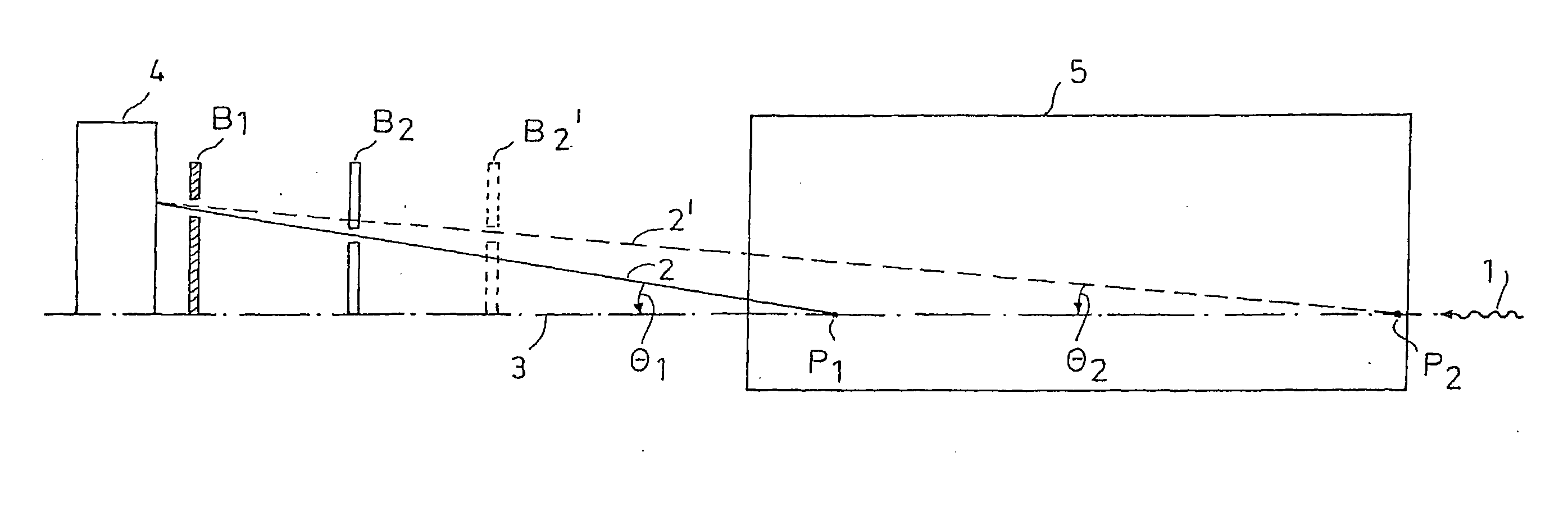
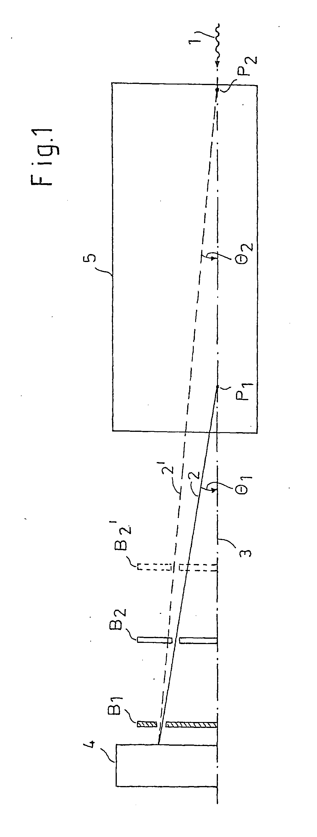
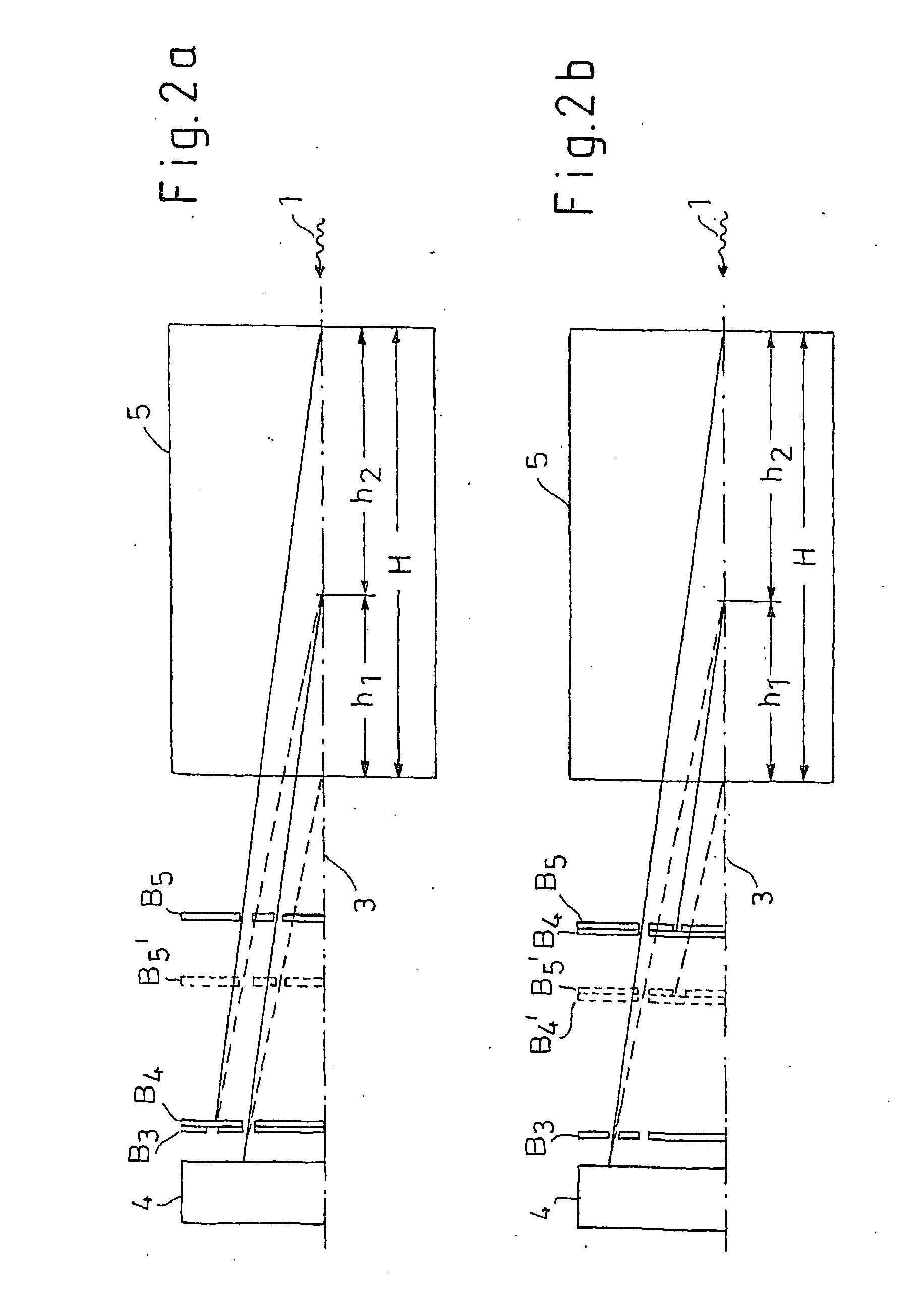
[0022]The figures show an operating mode of a collimator with an adjustable focal length with at least two diaphragms, each with at least one substantially circular slot about a common central axis, whereby at least one diaphragm can be displaced along the central axis. The collimator is used in an x-ray inspection system for detecting explosives. For reasons of clarity, a few elements, such as, for example, the housing of the collimator, were omitted. As far as is expedient, in the figures the same elements are provided with the same reference characters.

[0023]In both exemplary embodiments, an object 5 is to be examined along axis 3 for critical substances. Axis 3 is simultaneously the rotation axis of the diffraction phenomenon and the central axis for the diaphragms and their substantially circular slots. Object 5 to be examined is radiated with a pencil beam 1 of broad-band x-radiation along axis 3, whereby the radiation is diffracted in object 5. Then, diffraction spectra are t...


PUM

PropertyMeasurementUnit
focal lengthaaaaaaaaaa
spectraaaaaaaaaaa
atomic lattice distanceaaaaaaaaaa

Abstract

The invention relates to a collimator with adjustable focal length, especially for use in X-ray testing devices whose operating principle is based on diffraction phenomena in an object. Fixed focal length collimators used in such X-ray testing devices have to be displaced over a large range. The aim of the invention is to reduce the range of displacement. For this purpose, the collimator has at least two diaphragms having respective substantially circular slots arranged about a common center axis, wherein at least one diaphragm can be displaced along the center axis.

Description

[0001]This nonprovisional application is a continuation of International Application No. PCT / EP2006 / 000396, which was filed on Jan. 18, 2006, and which claims priority to German Patent Application No. DE 102005016656, which was filed in Germany on Jan. 26, 2005, and which are both herein incorporated by reference.BACKGROUND OF THE INVENTION[0002]1. Field of the Invention[0003]The present invention relates to a collimator with an adjustable focal length, particularly in x-ray inspection systems.[0004]2. Description of the Background Art[0005]Inspection methods with the use of x-rays are employed particularly in the detection of critical substances and objects in luggage or other freight. For this purpose, multi-stage systems are known whose first stage is based on the absorption of x-radiation. To detect certain critical substances such as, for example, explosives, a second stage is employed to which objects from the first stage are selectively supplied. Systems whose operating princ...

Claims


Application Information

Patent Timeline
Patent Type & Authority Applications(United States)
IPC IPC(8): G01N23/04G21K1/04
CPCG21K1/025
Inventor HAUNSCHILD, NORBERTHERDA, ULLRICHSIEDENBURG, UWEHARTICK, MARTINSCHALL, PATRICIA
Owner SMITHS HEIMANN
Why Eureka
Try Eureka