
Lens module socket

a technology of lens module and socket, which is applied in the direction of mountings, television systems, instruments, etc., can solve the problems of difficulty in meeting the compact size requirement of electronic products, and achieve the effect of reducing the total height of the assembly

Inactive Publication Date: 2011-07-28
CHENG UEI PRECISION IND CO LTD
View PDF3 Cites 0 Cited by
  • Summary
  • Abstract
  • Description
  • Claims
  • Application Information

AI Technical Summary

Benefits of technology

As described above, when the rotatable latch is rotated inwardly to the closed state, the press portion tightly presses against the top of the base portion to make the lens module received in the insulating housing without the space formed between the bottom base and a bottom of the lens module, which reduces the total height of the assembly of the lens module socket and the lens module.

Problems solved by technology

Therefore, it is difficult to fulfill the compact size requirement of the electronic products.

Method used


Image

  • Lens module socket
  • Lens module socket
  • Lens module socket

Examples


Embodiment Construction

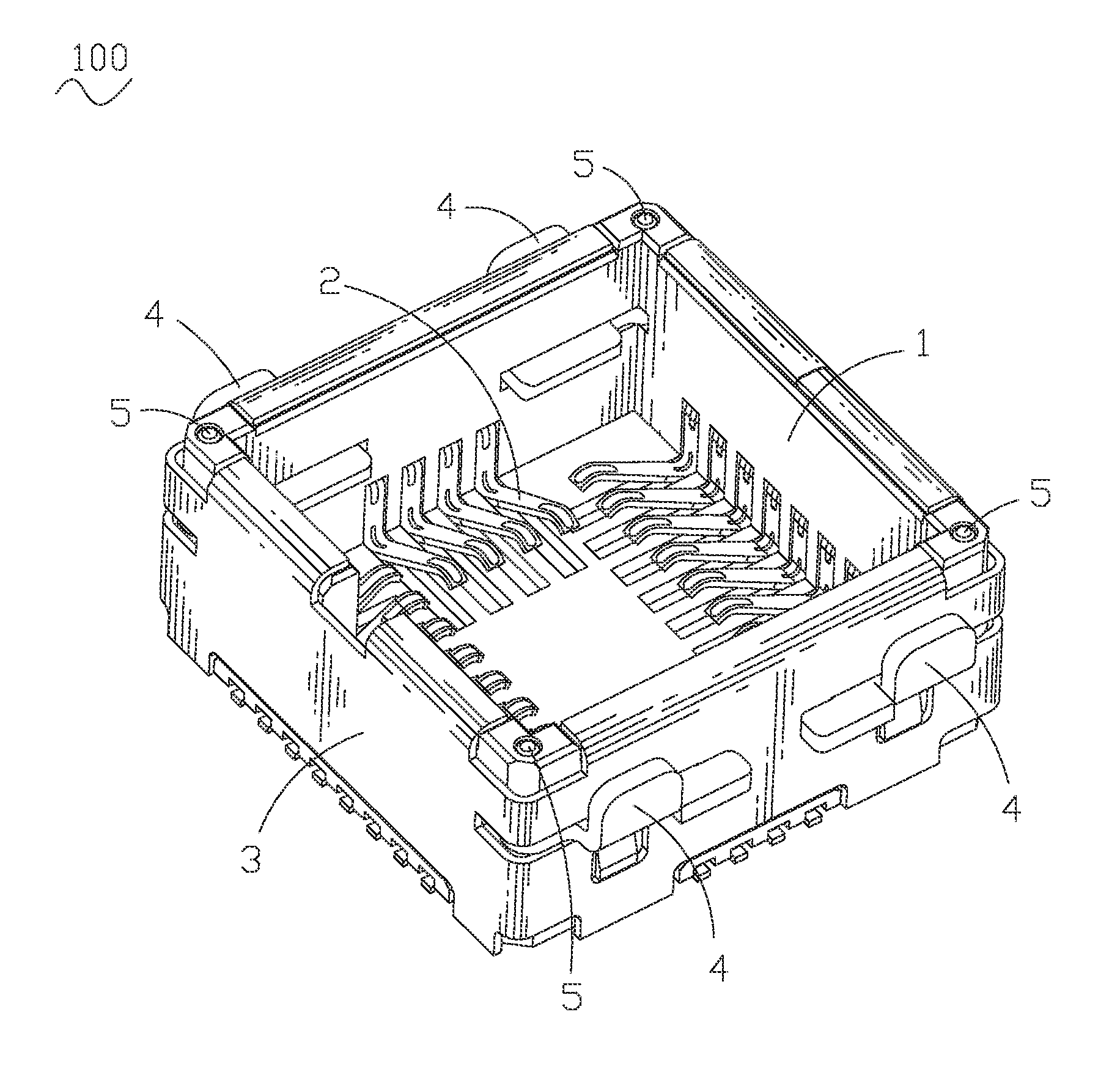
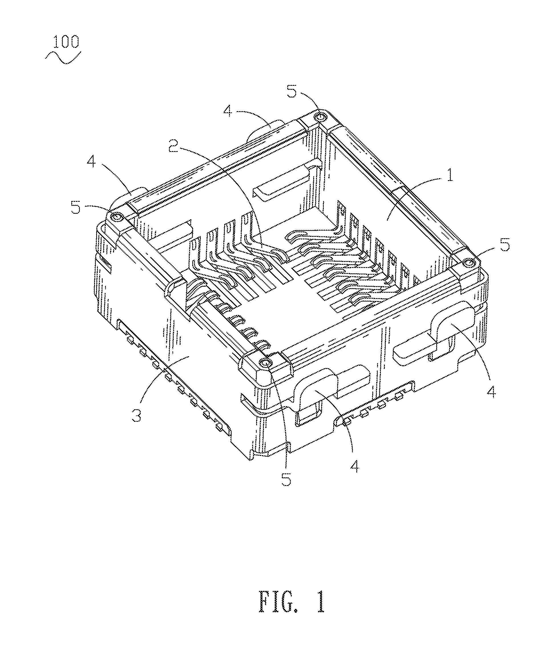
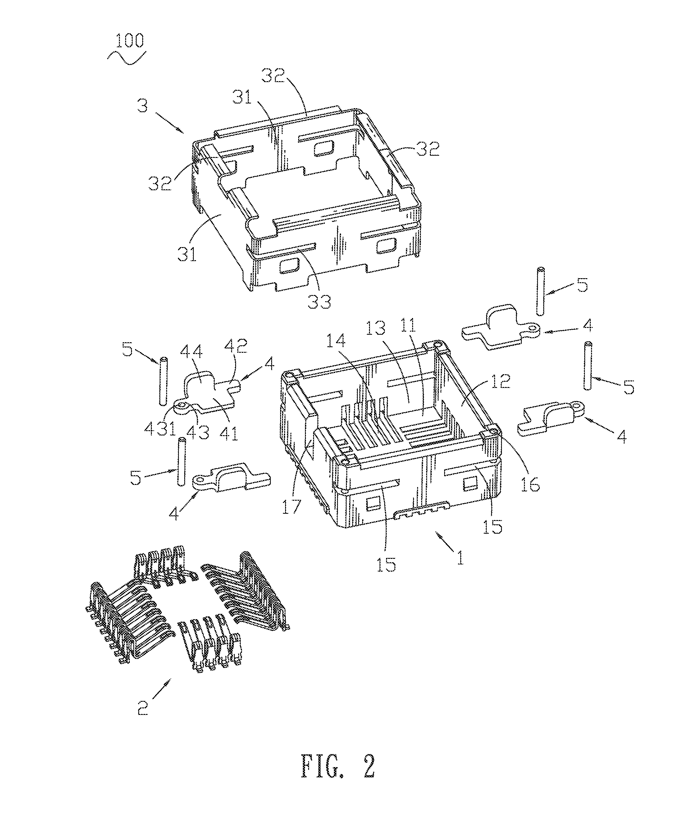
With reference to FIG. 1 and FIG. 2, a lens module socket 100 according to the present invention includes an insulating housing 1, a plurality of conductive terminals 2 received in the insulating housing 1, a shielding shell 3 encircling the insulating housing 1, and a plurality rotatable latches 4 pivotally assembled to the insulating housing 1 by a plurality of shaft pins 5.

The insulating housing 1 has a flat bottom base 11 and four side walls 12 respectively extended upwardly from four sides of the bottom base 11 to surround a receiving chamber 13 therebetween. The bottom base 11 defines a plurality of terminal grooves 14 extended to the side walls 12 for receiving a plurality of conductive terminals 2. The insulating housing 1 defines a plurality of slits 15 substantially parallel to the bottom base 11 and penetrating through two opposite side walls 12 to communicate with the receiving chamber 13. Furthermore, an inside of one end of each slit 15 is blocked by an adjacent side w...


PUM


Abstract

A lens module socket for receiving a lens module having a base portion includes an insulating housing, a plurality of conductive terminals received in the insulating housing, a shielding shell encircling the insulating housing, and a plurality of rotatable latches pivotally assembled to the insulating housing by a plurality of shaft pins. The insulating housing has a bottom base and side walls extended upwardly from the bottom base to surround a receiving chamber therebetween for receiving the lens module. The insulating housing defines a plurality of slits at the side walls for receiving the rotatable latches and a plurality of insertion holes extended downwardly from top portions of the side walls for receiving the shaft pins. The rotatable latches have press portions passing through the slits into the receiving chamber for pressing against the base portion of the lens module when the rotatable latches are rotated to a closed state.

Description

BACKGROUND OF THE INVENTION1. Field of the InventionThe present invention relates to a lens module socket, and more particularly to a lens module socket for receiving a lens module to reduce the total height of the assembly thereof.2. The Related ArtBecause of the development of wireless communication and the rapid revolution in high technology, portable electronic products, such as mobile phones, PDAs and notebook computers, are assembled with different electronic additional-modules such as lens modules for taking pictures and satisfying desires of consumers. Correspondingly, the lens module sockets spring up for the lens modules.In general, a lens module socket includes an insulating housing defining a receiving chamber therein for receiving a lens module, a plurality of conductive terminals received in the insulating housing, and a shielding shell encircling the insulating housing. The insulating housing has a bottom base and four side walls extended upwardly from the bottom base...

Claims


Application Information

Patent Timeline
Patent Type & Authority Applications(United States)
IPC IPC(8): G02B7/02
CPCG02B13/001H04N5/2257H04N5/2254H04M1/0264H04N23/57H04N23/55
Inventor WANG, CHIN-CHOU
Owner CHENG UEI PRECISION IND CO LTD
Learn More