Structure for mounting a clip for a writing implement

a writing implement and structure technology, applied in the field of structure for mounting a clip for a writing implement, can solve the problems of device description, relative awkwardness, drawbacks,

Active Publication Date: 2011-07-28
SOC DITE SOC BIC
View PDF4 Cites 1 Cited by
  • Summary
  • Abstract
  • Description
  • Claims
  • Application Information

AI Technical Summary

Benefits of technology

[0005]The embodiments of the present invention aim to resolve these drawbacks. To do this, the embodiments of the invention aim to provide a mounting structure for a writing implement which allows at least partial mounting of a clip, manually and without difficulty, in the required axial align...

Problems solved by technology

However, the device described in Japanese utility model JP51061936U presents drawbacks.
This operation is generally carried out manually and proves to be relatively awkward.
In fact, it is not easy to achieve the required axial alignment of the clip vis-à-vis the recesses, which increases the time required for mounting.
T...

Method used


Image

  • Structure for mounting a clip for a writing implement
  • Structure for mounting a clip for a writing implement
  • Structure for mounting a clip for a writing implement

Examples


first embodiment

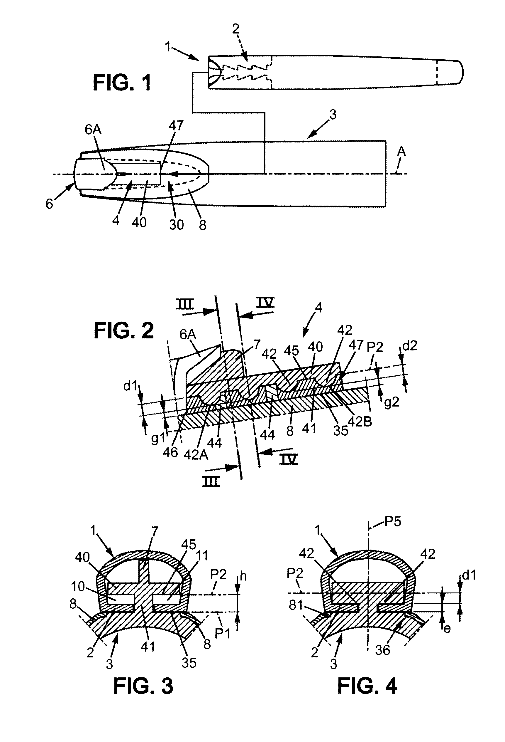
[0011]FIG. 1 diagrammatically represents a top view of a mounting structure according to the embodiments of the invention, together with a clip provided for mounting on a cap via the mounting structure.

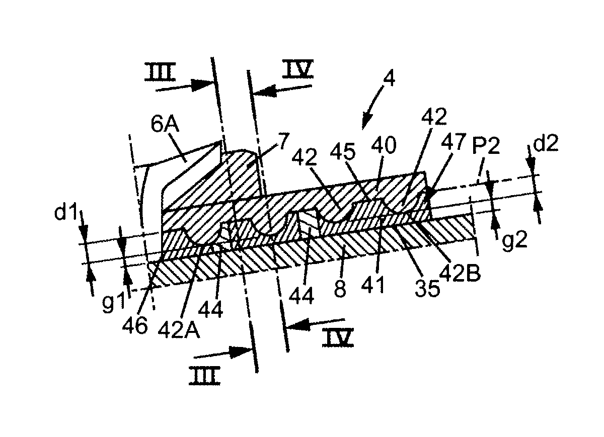
[0012]FIG. 2 diagrammatically represents the mounting structure of FIG. 1 in a partial side view with the clip not shown.

[0013]FIG. 3 diagrammatically represents a partial cross-section view of the mounting structure in the plane III-III of FIG. 2 with the clip mounted on the fastening member.

[0014]FIG. 4 diagrammatically represents a partial cross-section view of the mounting structure in the plane IV-IV of FIG. 2 with the clip mounted on the fastening member.

second embodiment

[0015]FIG. 5 diagrammatically represents a mounting structure according to the embodiments of the invention, in which the lower and upper walls of the fastening member both have bosses.

[0016]FIG. 6 represents a perspective bottom view of the clip of FIG. 1.

third embodiment

[0017]FIG. 7 diagrammatically represents a mounting structure according to the embodiments of the invention, in which the recess of the fastening member of the structure is closed laterally.

[0018]FIG. 8 diagrammatically represents a partial cross-section view of the mounting structure in the plane VIII-VIII of FIG. 7 with the clip mounted on the structure.


PUM


Abstract

A structure for mounting a clip for a writing implement which has a barrel extending along a longitudinal axis. The structure includes a fastening member made of plastic material integral with the barrel and having a proximal wall and a distal wall with respect to the barrel, the proximal and distal walls being arranged opposite each other and overall extending in substantially parallel respective planes in order to form between them a recess having an open insertion end. The clip includes a fastening portion having a substantially uniform thickness and is suitable for mounting in the recess by the open insertion end.

Description

CROSS REFERENCE TO RELATED APPLICATION[0001]This application is a national stage application of International Application No. PCT / FR2009 / 051698, filed on Sep. 9, 2009, which claims the benefit of French Patent Application No. 0856078 filed on Sep. 10, 2008, the entire contents of both applications being incorporated herein by reference.FIELD OF INVENTION[0002]The embodiments of the present invention generally relate to a structure for mounting a clip for a writing implement having a barrel extending along a longitudinal axis, that includes a fastening member made of plastic material integral with the barrel, that includes a proximal wall and a distal wall with respect to the barrel arranged opposite each other and essentially extending in substantially parallel planes respectively, in order to form between them a recess which has an open insertion end. The clip also includes a fastening portion that has a substantially uniform thickness and is suitable for mounting in the recess via...

Claims


Application Information

Patent Timeline
IPC IPC(8): F16B2/20
CPCB43K25/022B43K23/126
Inventor ROLION, FRANCKBEAUCHER, LAURENT
Owner SOC DITE SOC BIC
Why Eureka
Try Eureka