
Cooperative communication method and base station thereof

a communication method and cooperative technology, applied in the field of cooperative communication methods and cooperative communication methods, can solve the problems of deteriorating communication performance, user equipment positioned in the boundary between the evolved node b and the relay station has lower transmission/reception performance than a user equipment positioned at the center of the cell, and drastic decline in communication performance in the cell boundary, so as to improve the communication performance of user equipmen

Inactive Publication Date: 2011-07-21
ELECTRONICS & TELECOMM RES INST
View PDF11 Cites 81 Cited by
  • Summary
  • Abstract
  • Description
  • Claims
  • Application Information

AI Technical Summary

Benefits of technology

The present invention provides a method for improving communication performance in a mobile communication system by using multiple cells and a cooperative communication approach. This approach involves comparing channel state information for a radio signal with a predetermined threshold value to determine if a user equipment should be served by a cooperating cell. The cooperating cell can be a relay station or an evolved Node B. The use of multiple cells and a cooperative communication approach expands the communication coverage and capacity of the system.

Problems solved by technology

In a mobile communication system, a user equipment positioned in the cell boundary where the intensity of radio signals are weak has a problem of deteriorated communication performance.
In particular, when a relay station is used to communicate with the user equipment positioned in the cell boundary where the intensity of radio signals are weak, there is a problem in that a user equipment positioned in the boundary between the evolved Node B and the relay station has lower transmission / reception performance than a user equipment positioned at the center of a cell.
Also, since the next-generation mobile communication system uses high frequency domain and an OFDM communication scheme whose communication performance is considerably deteriorated in the cell boundary, there is a problem of drastic decline in the communication performance in the cell boundary.

Method used

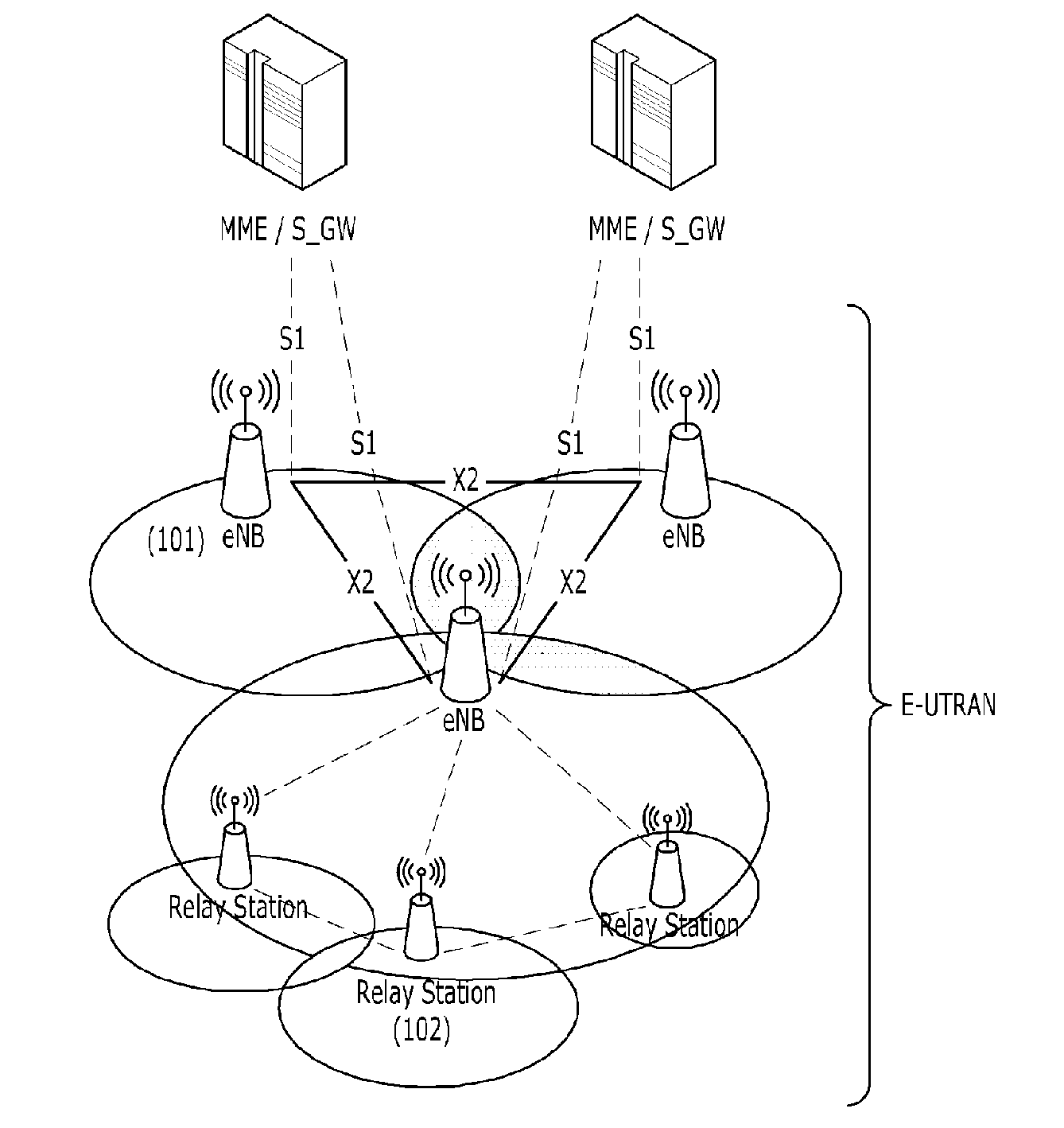
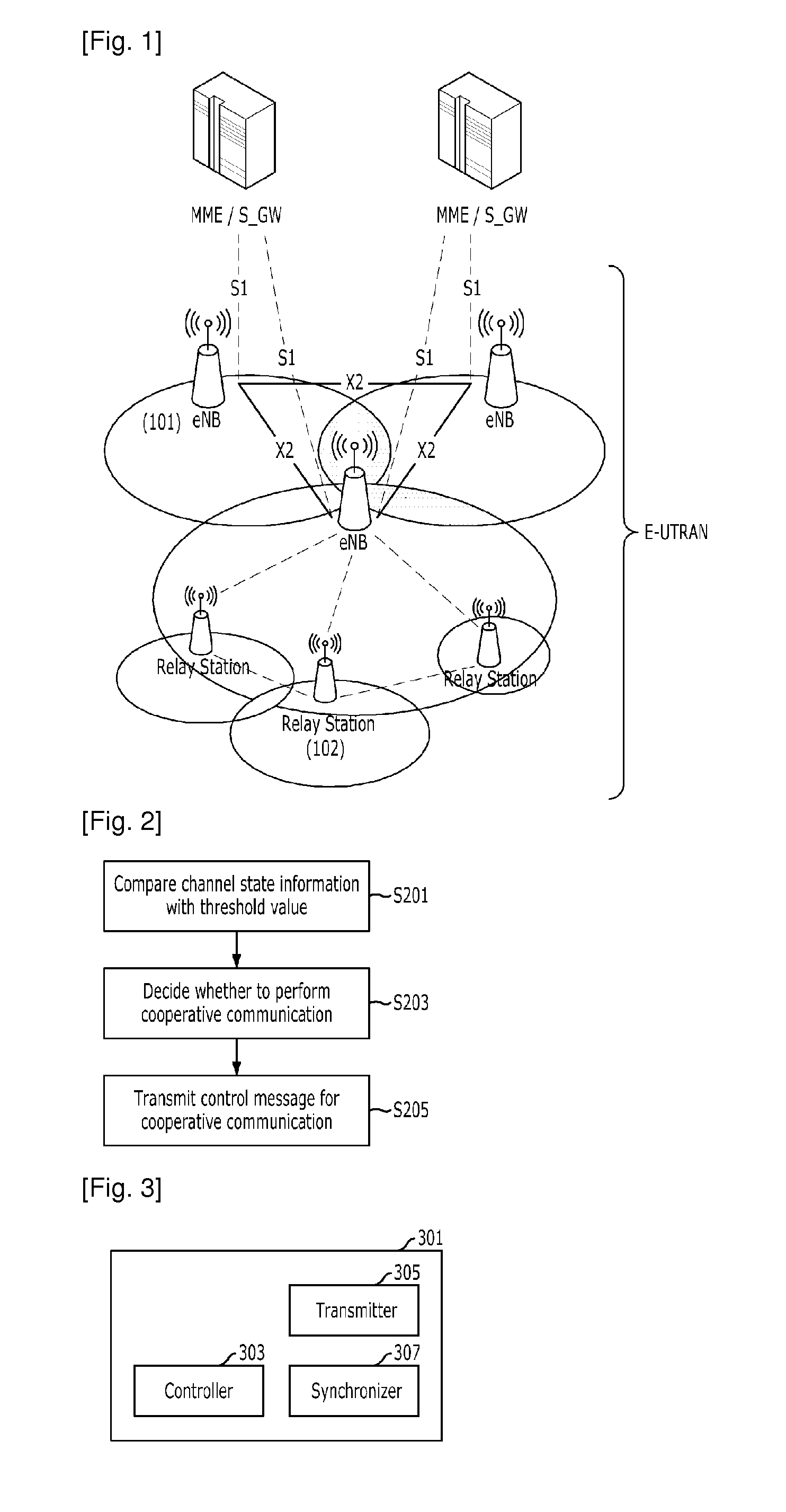
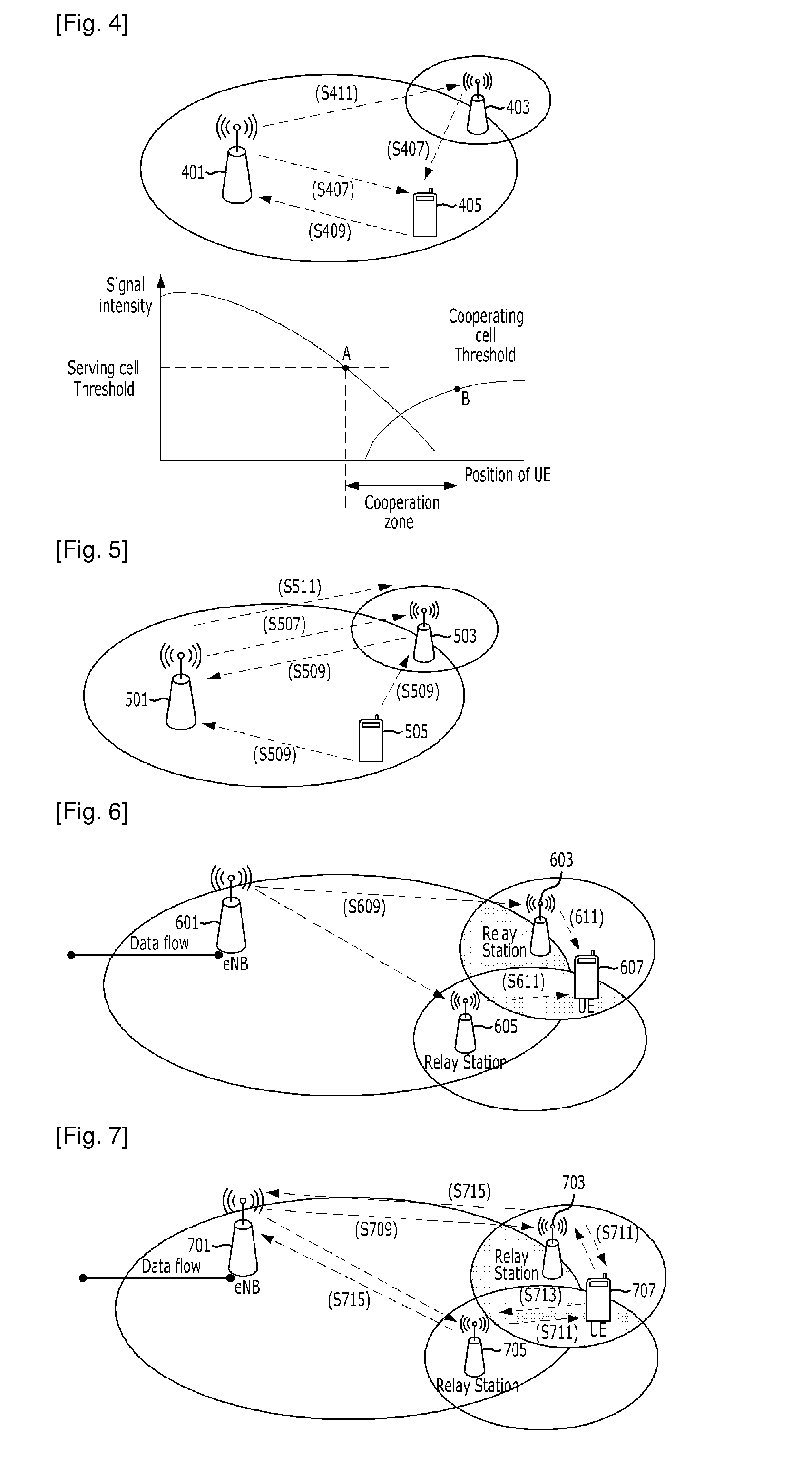

Image

  • Cooperative communication method and base station thereof
  • Cooperative communication method and base station thereof
  • Cooperative communication method and base station thereof

Examples


Embodiment Construction

[0026]The advantages, features and aspects of the invention will become apparent from the following description of the embodiments with reference to the accompanying drawings, which is set forth hereinafter. Also, when it is considered that detailed description on the prior art may obscure a point of the present invention, the description will not be provided in this specification. Hereafter, specific embodiments of the present invention will be described with reference to the accompanying drawings.

[0027]Following description exemplifies only the principles of the present invention. Even if they are not described or illustrated clearly in the present specification, one of ordinary skill in the art can embody the principles of the present invention and invent various apparatuses within the concept and scope of the present invention. The use of the conditional terms and embodiments presented in the present specification are intended only to make the concept of the present invention un...


PUM


Abstract

A cooperative communication method for cooperative communication with a user equipment by using a plurality of cells and a base station used for the cooperative communication are disclosed. The method for performing a cooperative communication for a user equipment by using a plurality of cells includes: comparing channel state information for a radio signal with a predetermined threshold value to thereby produce a comparison result; determining whether to perform the cooperative communication for the user equipment based on the comparison result; and transmitting a control message for cooperative communication to a cooperating cell which is to perform the cooperative communication.

Description

TECHNICAL FIELD[0001]The present invention relates to a cooperative communication method and a base station thereof; and, more particularly, to a cooperative communication method for cooperative communication with a user equipment by using a plurality of cells and a base station used for the cooperative communication.BACKGROUND ART[0002]The 3rd Generation Partnership Project (3GPP), which is an organization for mobile telecommunication standardization, is working on a Long Term Evolution (LTE) standardization activity to develop a next-generation mobile communication system specification. The 3GPP is also developing LTE Advanced specification which supplements LTE specification in order to fulfill the IMT-advanced requirements suggested by International Telecommunication Unit Radio communication sector (ITU-R).[0003]The next-generation mobile communication system uses an Orthogonal Frequency Division Multiple Access (OFDMA) in the downlink and uses OFDMA or Single Carrier Frequency ...

Claims


Application Information

Patent Timeline
Patent Type & Authority Applications(United States)
IPC IPC(8): H04B7/14H04W72/04H04W36/00
CPCH04B7/024H04B7/15592H04W84/047H04W72/08H04W72/0413H04B7/022H04W72/54H04W72/21H04L5/0035
Inventor LEE, KYOUNGSEOKAHN, JAE-YOUNGKIM, YEONGJIN
Owner ELECTRONICS & TELECOMM RES INST
Learn More