
Dynamic firearm

a firearm and dynamic technology, applied in the field of firearms, can solve the problems of reducing reliability, irrational, complex and irrational automatic firing and reloading,

Inactive Publication Date: 2011-07-21
DONETABKY YURIJ IGOREVICH
View PDF10 Cites 1 Cited by
  • Summary
  • Abstract
  • Description
  • Claims
  • Application Information

AI Technical Summary

Benefits of technology

"The present invention improves the efficiency of recoil energy absorption and damping of weapon oscillation after firing. It simplifies the design and reduces the weight of the weapon. It improves reliability and pattern of automatic shooting. It automatically loads in case of misfire. It allows for adjustable firing rate. The invention includes a firing mechanism that can hold the barrel in the extreme recoil position and fire during the recoil or counterrecoil, a gun carriage with guides for the breech block flanges, an extractor to stop the projectile and eject it from the barrel during counterrecoil, a recoil imitator to move the barrel to the extreme recoil position, a projectile holder to hold the projectile in place during barrel movement, a device to feed the projectile holder with projectiles, and a guiding deflector to change the movement direction of the spent cartridge case."

Problems solved by technology

The firing and reload automation is quite complex and irrational.
In the same time the automation design is more complicated compared to the stationary barrel weapon (e.g. the AKM assault rifle), reducing its reliability, increasing its manufacturing laboriousness and making the operation more complicated.
The recoiling parts of the weapon have a significant weight—its moving and hitting in the front and rear positions cause significant oscillation of the weapon and considerable scattering of projectiles.
Implementation of reload automation does not improve the rate of fire and is considered impractical.

Method used


Image

  • Dynamic firearm
  • Dynamic firearm
  • Dynamic firearm

Examples


Embodiment Construction

[0024]While the invention may be susceptible to embodiment in different forms, there are shown in the drawings, and will be described in detail herein, specific embodiments of the present invention, with the understanding that the present disclosure is to be considered an exemplification of the principles of the invention, and is not intended to limit the invention to that as illustrated and described herein.

[0025]A preferred embodiment of the firearm comprises:

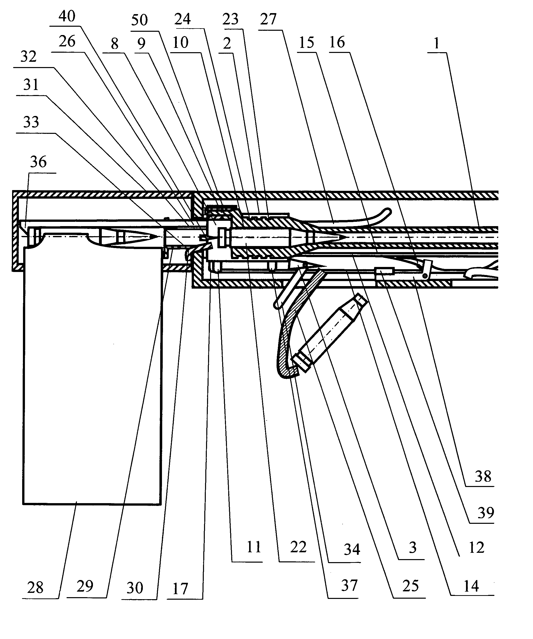
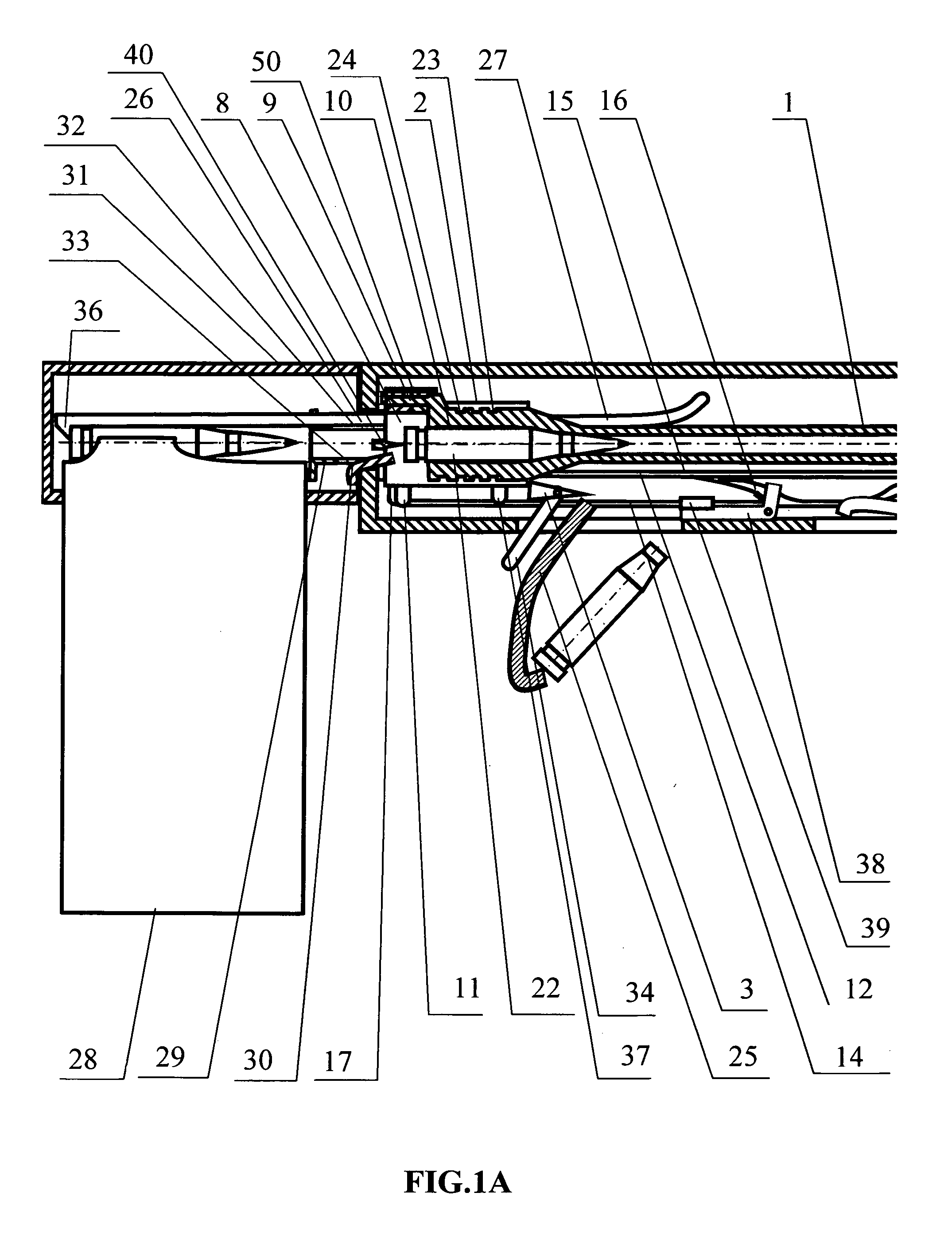
Barrel (1) (illustrated on FIGS. 1a and 1b) with breech block (2) in the gun carriage, firing mechanism, with check (3) being a part of it, with lever (34), gun carriage (13) with antirecoil mechanism (4).

[0026]Dynamic weapon works as follows. Barrel (1) (FIG. 1a) with breech block (2) is held in the extreme recoil position with check (3) preventing it from counterrecoil by the action of antirecoil mechanism (4) (FIG. 1b), placed around the barrel (1) (FIG. 1a), where piston (5) (FIG. 1b) is installed. Piston (5), through bra...


PUM


Abstract

In weapon shot is fired during counterrecoil. The counterrecoil energy damps the recoil energy. During recoil, the breech block is unlocked, the spent cartridge case is ejected from the barrel by the residual pressure of the powder gases and is directed by a deflector into a hole in the gun carriage. When recoiling into the aftmost position, the barrel approaches the projectile and locks it by means of the breech block. Meanwhile, the next cartridge is taken from a magazine. In the event of misfire, the barrel, continuing to counterrecoil, actuates an extractor for removing the defective projectile. A recoil imitator returns the barrel to the aftmost position, where it is loaded with a projectile in a manner similar to the post-firing recoil. The technical result is ability to load the weapon automatically before firing or to reload the weapon automatically in the event of misfire.

Description

CROSS-REFERENCES TO RELATED APPLICATIONS[0001]This application is a U.S. national phase application of a PCT application PCT / RU2009 / 000656 filed on 27 Nov. 2009, published as WO2010 / 041985, whose disclosure is incorporated herein in its entirety by reference, which PCT application claims priority of a Russian Federation patent application RU2008139537 filed on 7 Oct. 2008.FIELD OF THE INVENTION[0002]This invention belongs to the field of firearms. It can be used as an artillery weapon or a small arms weapon.BACKGROUND OF THE INVENTION AND RELATED ART[0003]As a rule, an artillery weapon has a barrel with breech block in breeching, firing mechanism and gun carriage with antirecoil mechanism. To fire a shot, the projectile is manually inserted into the barrel breeching, the breech block locks the barrel channel and shot is fired through the firing mechanism. The barrel and breech block move backwards due to recoil. The antirecoil mechanism allows dampening the recoil energy many fold, ...

Claims


Application Information

Patent Timeline
Patent Type & Authority Applications(United States)
IPC IPC(8): F41A25/00F41A15/00F41A3/00F41A9/00
CPCF41A3/04F41A9/46F41A15/20F41A15/16F41A15/18F41A9/54
Inventor DONETSKY, YURIJ IGOREVICH
Owner DONETABKY YURIJ IGOREVICH
Learn More