
Synchronized video and synthetic visualization system and method

a synthetic visualization and video technology, applied in the field of synchronized video and synthetic visualization system and method, can solve the problems of life and death consequences, bulky and expensive electro-mechanical platform, and impracticality for private home us

Active Publication Date: 2011-07-14
APPAREO SYST
View PDF91 Cites 55 Cited by
  • Summary
  • Abstract
  • Description
  • Claims
  • Application Information

AI Technical Summary

Benefits of technology

[0012]An alternative embodiment of the present invention uses recovered synched simulation and video recorded data, along with recorded audio data from within the aircraft, to determine the source of a malfunction within an aircraft after an incident has occurred. Although high-quality simulation data of the flight is of great use when determining why an aircraft malfunctioned, real-time audio and video recording what was actually occurring in the cockpit at the time of the malfunction would be invaluable.

Problems solved by technology

However real the simulation may appear, the information produced is still only a simulation and cannot provoke the behaviors and responses of a student in a real airplane in a real life training situation whose behavior has life and death consequences.
Neither can a simulation provide the sensory perception imparted to a person in flight by an actual airplane that is acted upon by external stimulations such as weather, loading, and altitude; although existing simulation programs do include weather information accurately based on particular dates and times, but this information does not impart actual sensory perception to simulation pilots.
The addition of movement and tactile feedback is a distinct improvement over a software-only system for flight training, but demands a complex, bulky, and expensive electro-mechanical platform to add even the simplest motion, making it impractical for private home use.
Graphical rendering has not yet reached the point where a 3D computer generated model can look as real as actual flight video.

Method used


Image

  • Synchronized video and synthetic visualization system and method
  • Synchronized video and synthetic visualization system and method
  • Synchronized video and synthetic visualization system and method

Examples


Embodiment Construction

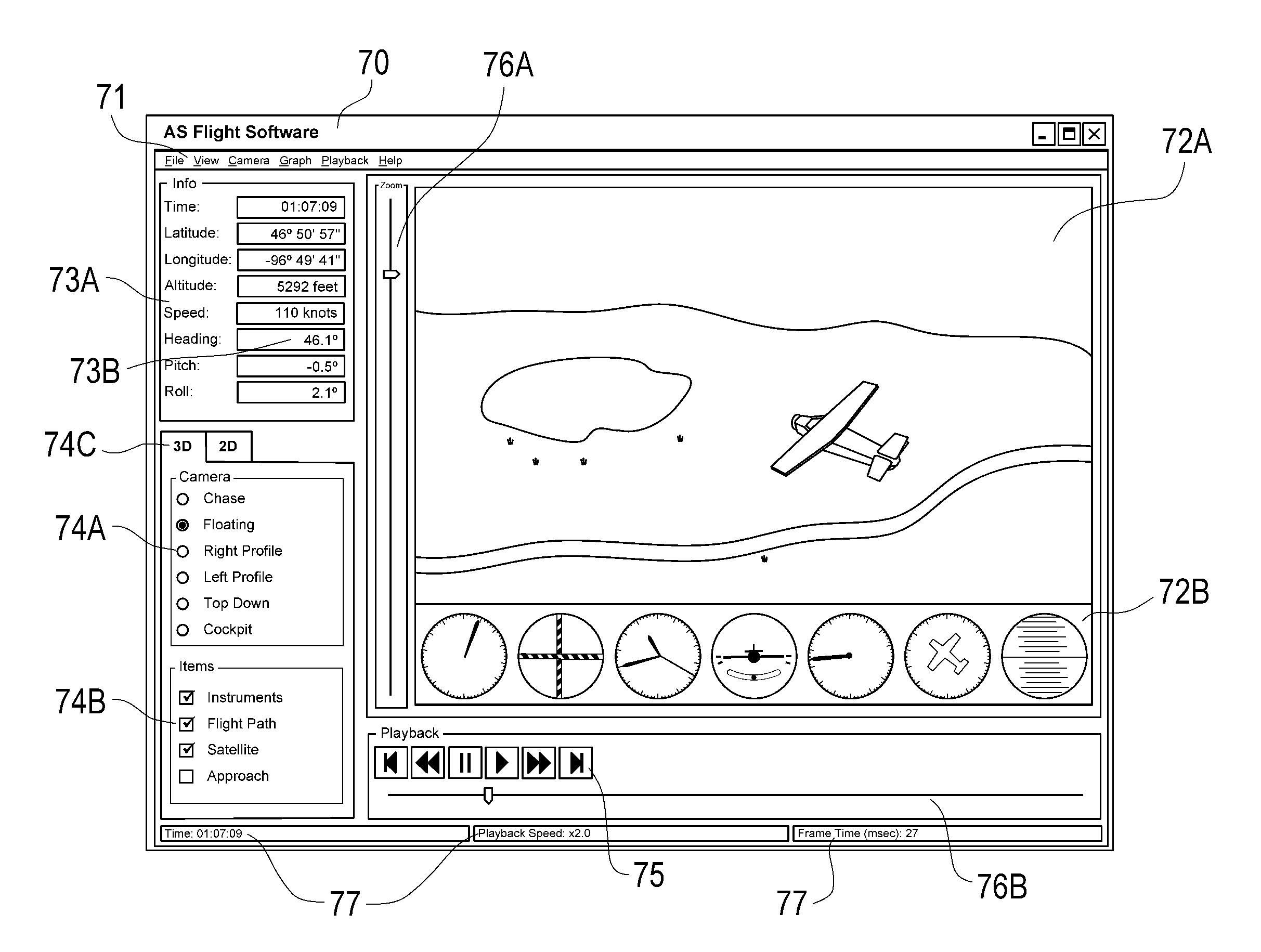
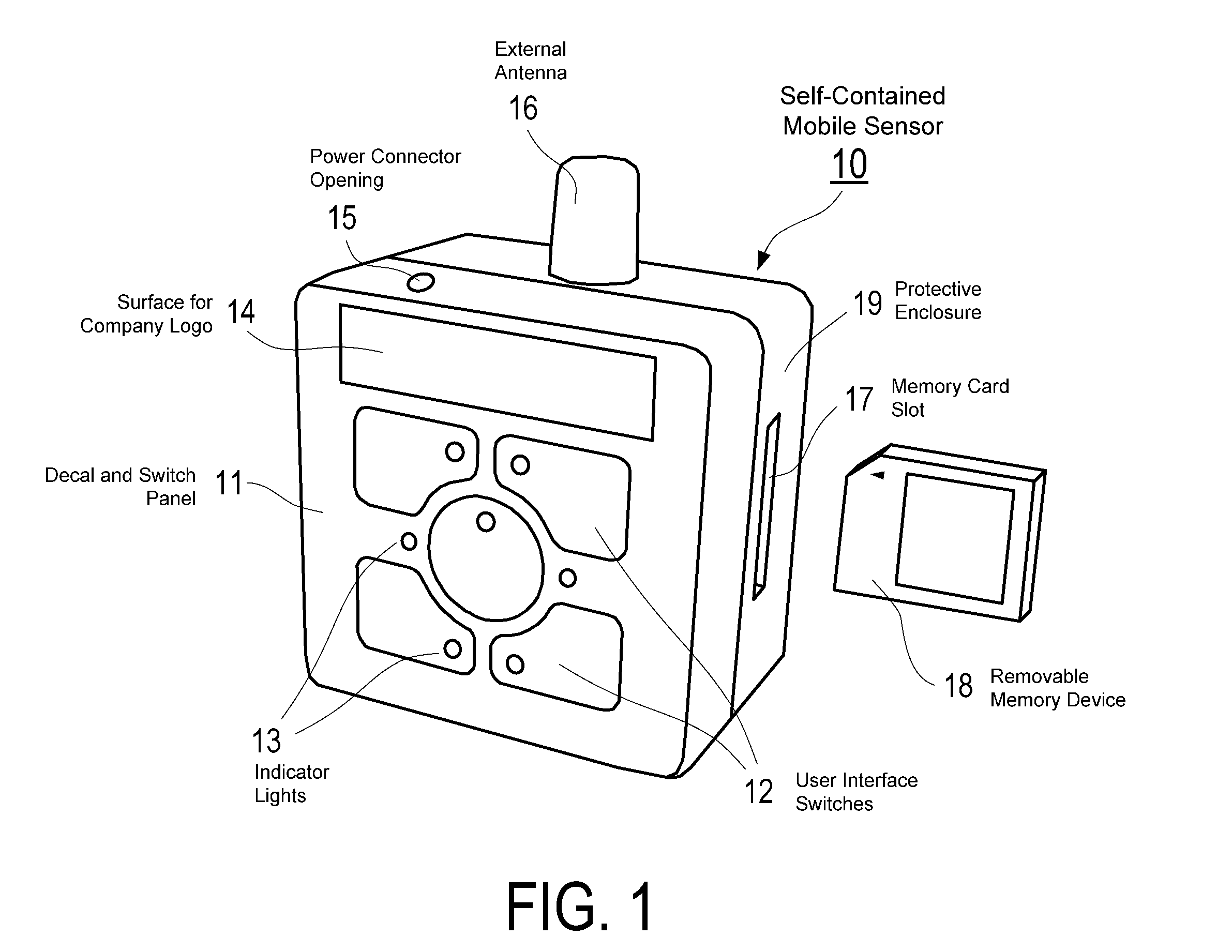
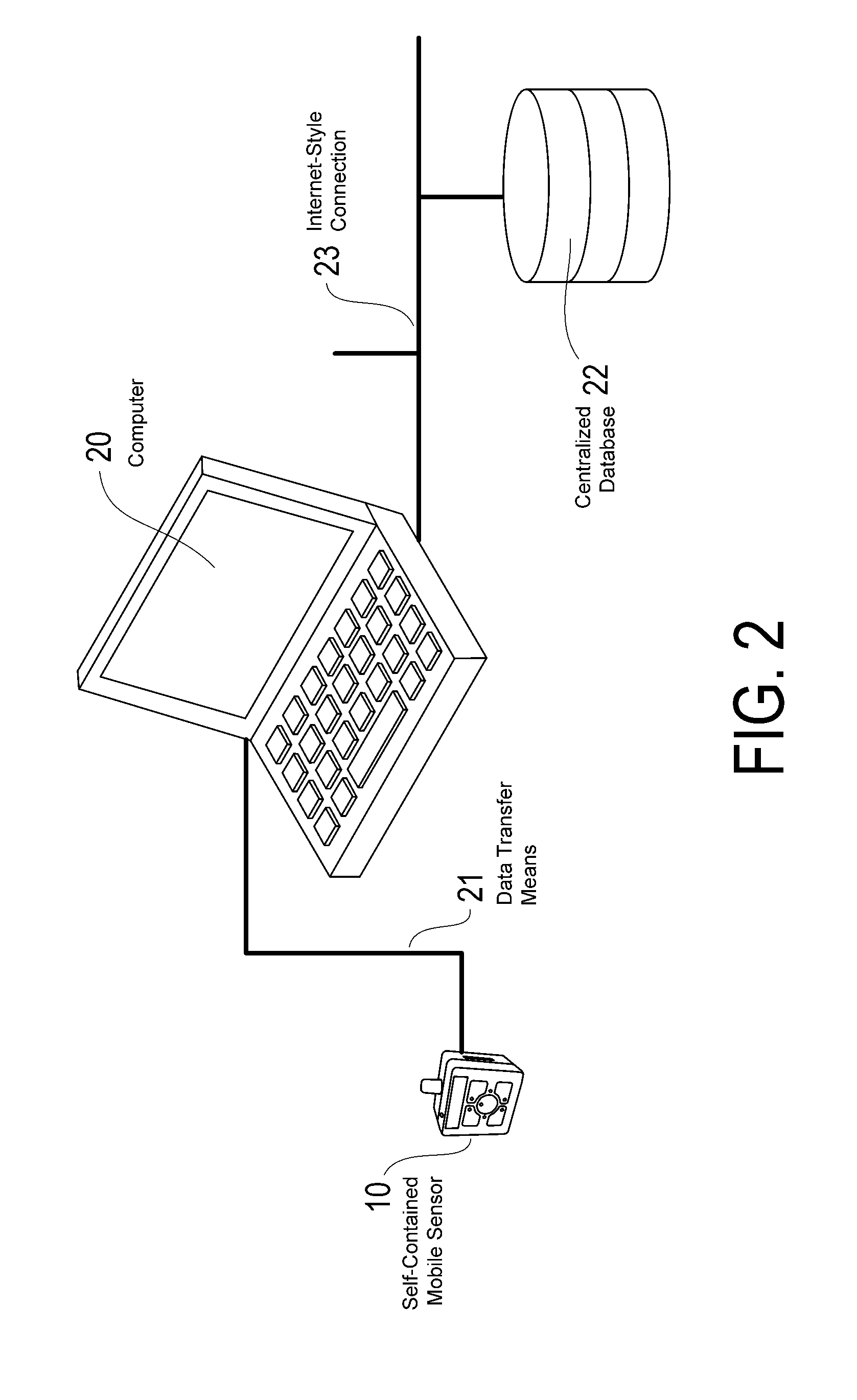
[0050]In the preferred embodiment, the flight training and synthetic visualization system is used primarily as a flight training aid, providing playback and analysis of flight data recorded by a mobile sensor (this embodiment is illustrated in FIG. 2). A user mounts the mobile sensor 10 in or on an aircraft or other moving object (the moving object could also be a person such as a skydiver). The mobile sensor 10 is turned on, the Record button is pressed, and recording begins. Once operational, the mobile sensor 10 follows the algorithm described in FIG. 10 (Steps 1000 through 1011), acquiring flight data describing the position and orientation of the mobile sensor 10 as it moves through three-dimensional space.

[0051]While it is recording, the mobile sensor 10 relies on a plurality of on-board sensors to obtain flight data. In the preferred embodiment (FIG. 6), the mobile sensor 10 comprises:[0052]a yaw accelerometer 600, a roll accelerometer 610, and a pitch accelerometer 620 to re...


PUM


Abstract

The present invention presents a flight training and synthetic visualization system, which comprises a fully mobile, self-contained data recording unit including a desktop graphics software engine for creating a virtual model of the flight capable of playing back the recorded trip, synchronized with a real-time video or imagery recording of the actual flight with a view from the cockpit of the aircraft as a pilot would actually view the flight, along with ambient audio of the cockpit. This allows for the user of the simulation to view both modeled data of the flight, as well as actual time-sequenced still images or video of the flight. The two sources of data are synched in time so that real video images of the aircraft as it is flying at a specific point in time is displayed in the simulation at the same moment as the rendered visualization of the flight.

Description

CROSS-REFERENCE TO RELATED APPLICATIONS[0001]This application claims priority in U.S. Provisional Patent Application No. 61 / 306,299 filed Feb. 19, 2010, which is incorporated herein by reference. This application is a continuation-in-part of and claims the benefit of U.S. patent application Ser. No. 12 / 961,612, entitled “Flight Training and Synthetic Visualization System and Method,” filed Dec. 7, 2010, which is a continuation of U.S. patent application Ser. No. 11 / 327,965, entitled “Flight Training and Synthetic Visualization System and Method,” filed Jan. 9, 2006, now U.S. Pat. No. 7,848,698, issued Dec. 7, 2010, and U.S. Provisional Patent Application No. 60 / 701,736, entitled, “Low-Cost Flight Training and Synthetic Visualization System,” filed Jul. 22, 2005.BACKGROUND OF THE INVENTION[0002]1. Field of the Invention[0003]The present invention pertains generally to a system and method for providing operator training through the synchronized playback of video recorded during a trip...

Claims


Application Information

Patent Timeline
IPC IPC(8): G09B9/08
CPCG09B9/08G09B19/165G09B9/30
Inventor GELINSKE, JOSHUA N.ALLEN, ROBERT M.BATCHELLER, BARRY D.HALVORSON, JACOB A.OHLSEN, TYLER C.SCHUBERT, SETH J.WEINMANN, ROBERT V.WIIG, JOHAN A.
Owner APPAREO SYST
Learn More