
Electronic Device Housing Having a Movable Foot Pad Mechanism

a technology of electronic devices and foot pads, which is applied in the direction of electric apparatus casings/cabinets/drawers, instruments, portable computers, etc., can solve the problems of electronic components within the housing body being damaged, the housing body becoming hot after a period of use, and the housing body being likely to become overheated, so as to enhance the heat dissipation effect of the devi

Active Publication Date: 2011-07-14
WISTRON CORP
View PDF14 Cites 11 Cited by
  • Summary
  • Abstract
  • Description
  • Claims
  • Application Information

AI Technical Summary

Benefits of technology

[0006]Therefore, an object of the present invention is to provide an electronic device housing having a movable foot pad mechanism that can overcome the heat-dissipating problems associated with the prior art. The movable foot pad mechanism is operable and movable to prop the device housing higher upward relative to a supporting surface so as to increase a heat-dissipating space between the device housing and the supporting surface.
[0008]One effect of the present invention resides in that, by operating the interfering member to cause the same to release the foot pad body, the foot pad body can automatically turn pivotally to the second direction state by virtue of the biasing force of the first spring so as to prop the bottom wall higher upward relative to the supporting surface in order to make more room available for heat dissipation.
[0010]Another effect of the present invention resides in that, by virtue of the connection and cooperation between the ventilation grille and the foot pad body, when the housing body is being propped upward, the interior space of the housing body can be simultaneously brought into fluid communication with the ambient environment, whereby the hot air inside the housing body can disperse downward through the ventilation grille and out of the bottom wall. By configuring the foot pad body to push the ventilation grille to cause the second air vents in the ventilation grille to be staggered relative to the first air vents when the foot pad body is disposed in the first direction state, an effect of preventing entry of dust or dirt into the housing body through the bottom wall can be achieved.
[0012]A further effect of the present invention resides in that, by virtue of the arrangement of the fan switch and the foot pad body, when the housing body is propped upward and the interior of the housing body is brought into fluid communication with the ambient environment, the fan can be activated at the same time to cause the hot air within the housing body to be quickly dissipated downwardly through the second air vents in the ventilation grille and through the first air vents in the bottom wall.

Problems solved by technology

However, for a notebook computer with a high operating efficiency, a housing body thereof will become hot after a period of use.
When the notebook computer is placed on a desktop for use, if there is not enough space between the housing body and the desktop for dissipation of heat, the housing body is likely to become over-heated.
In a worse case, the electronic components within the housing body may be damaged.
On the other hand, when the notebook computer is placed on the user's lap, the overheated housing body is likely to cause discomfort to the user's lap due to the heat, even to the extent that the user's lap may get burned.

Method used


Image

  • Electronic Device Housing Having a Movable Foot Pad Mechanism
  • Electronic Device Housing Having a Movable Foot Pad Mechanism
  • Electronic Device Housing Having a Movable Foot Pad Mechanism

Examples


Embodiment Construction

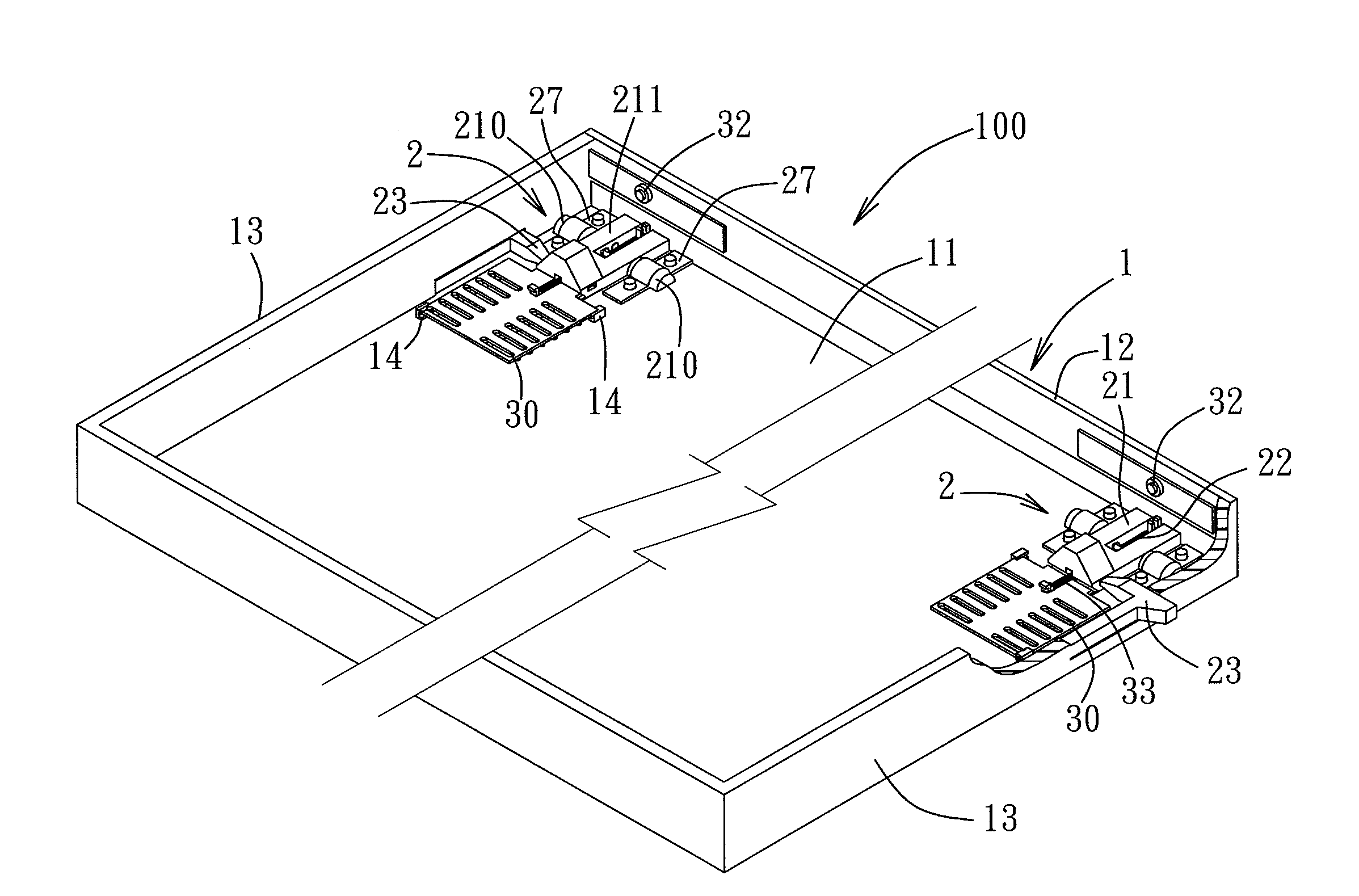
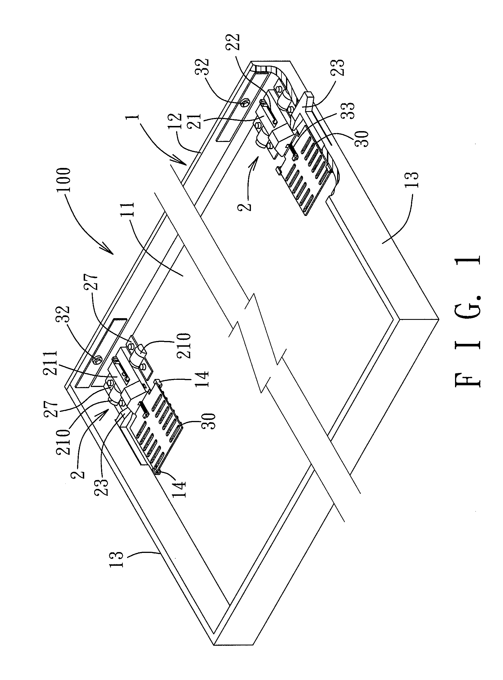
[0026]Referring to FIG. 1, the preferred embodiment of an electronic device housing 100 according to the present invention is shown to include a housing body 1 and two movable foot pad mechanisms 2 disposed in the housing body 1. The electronic device housing 100 may be a host housing of a notebook computer or a housing of any other electronic device. It should be noted herein that, in the drawings of the preferred embodiment, a top cover of the housing body 1 is omitted in order to better illustrate the structure of the movable foot pad mechanisms 2.

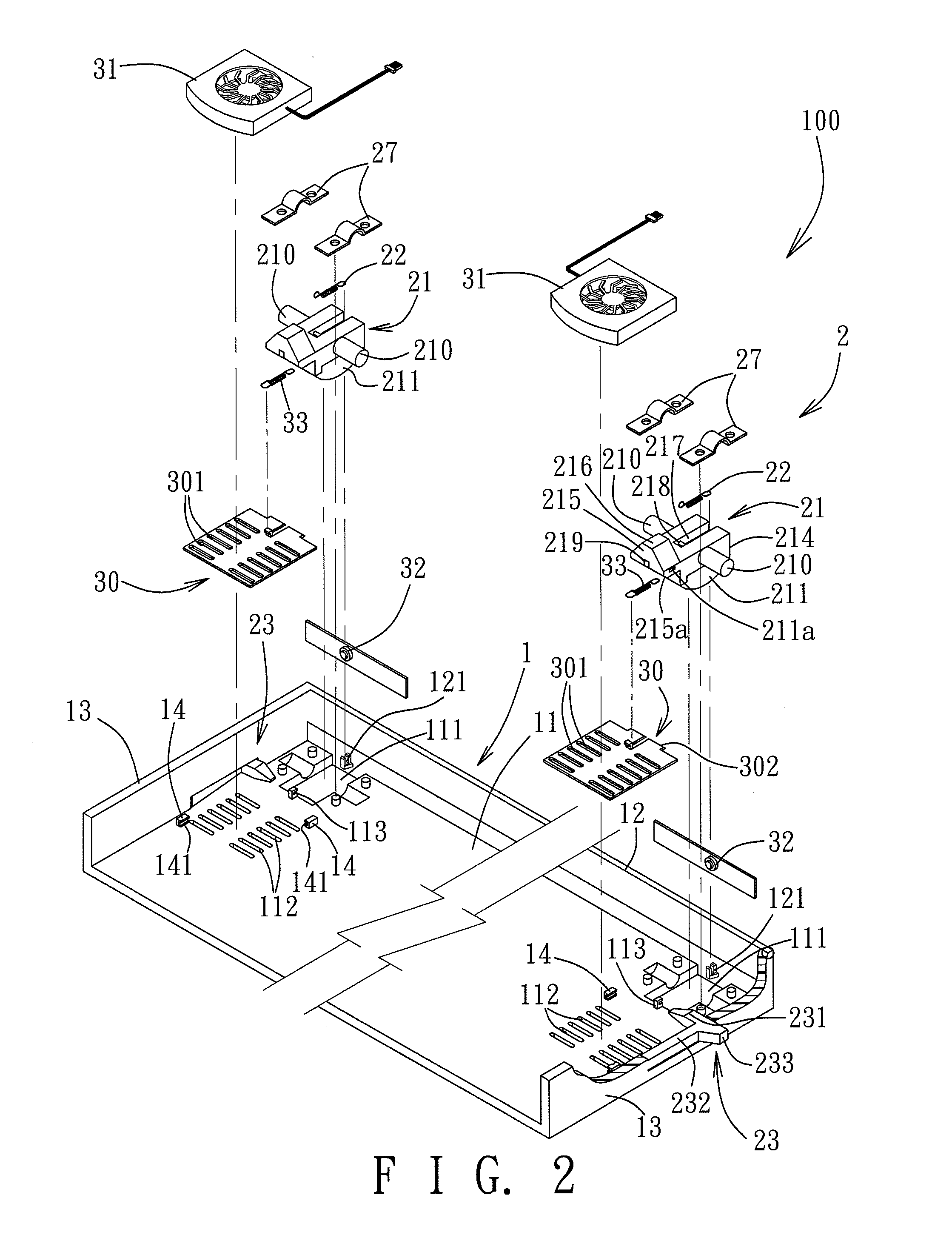
[0027]Referring to FIG. 2, the housing body 1 includes a bottom wall 11. The bottom wall 11 is provided with two openings 111. The two openings 111 are disposed respectively at left and right sides of the bottom wall 11. The two movable foot pad mechanisms 2 are disposed respectively at the openings 111 at the left and right sides of the bottom wall 11. Since the two foot pad mechanisms 2 are identical in construction, solely for the pu...


PUM


Abstract

An electronic device housing includes a housing body, a movable foot pad mechanism disposed in housing body, a ventilation grille, a fan, and a fan switch connected electrically to the fan. The movable foot pad mechanism includes a foot pad pivoted to a bottom wall of the housing body. The foot pad is turnable pivotally to prop up the housing body so as to increase a space below a bottom of housing body. When the foot pad is being turned pivotally to prop up the housing body, the ventilation grille is moved simultaneously so as to make the space inside the housing body open to the ambient environment, and the fan is activated for heat dissipation, thereby increasing the heat dissipation efficiency of the electronic device housing.

Description

CROSS-REFERENCE TO RELATED APPLICATION[0001]This application claims priority of Taiwanese Application No. 099100380, filed on Jan. 8, 2010.BACKGROUND OF THE INVENTION[0002]1. Field of the Invention[0003]The invention relates to a movable foot pad mechanism and an electronic device housing having the movable foot pad mechanism, more particularly to a movable foot pad mechanism capable of enhancing the heat-dissipating effect of an electronic device housing, and the electronic device housing.[0004]2. Description of the Related Art[0005]A conventional notebook computer may be placed on a supporting surface of a desk or on the lap of a seated user for use. However, for a notebook computer with a high operating efficiency, a housing body thereof will become hot after a period of use. When the notebook computer is placed on a desktop for use, if there is not enough space between the housing body and the desktop for dissipation of heat, the housing body is likely to become over-heated. In ...

Claims


Application Information

Patent Timeline
IPC IPC(8): H05K7/20H05K5/00
CPCG06F1/166H05K5/0204G06F1/203
Inventor CHENG, WEN-CHIEHWANG, CHIH-YI
Owner WISTRON CORP
Learn More