
Power feed device, power receiving device, and wireless power feed system

a technology of power receiving device and wireless power feed system, which is applied in the direction of near-field systems using receivers, resonant antennas, inductances, etc., can solve the problems of large loss, large loss, and large loss, and achieve the effect of low loss

Inactive Publication Date: 2011-07-14
SONY CORP
View PDF4 Cites 68 Cited by
  • Summary
  • Abstract
  • Description
  • Claims
  • Application Information

AI Technical Summary

Benefits of technology

The present invention provides a power feed device, power receiving device, and wireless power feed system capable of impedance matching with low loss. The device includes a power feed element and a resonance element coupled by electromagnetic induction, and a variable matching unit capable of changing the diameter of the power feed element to achieve impedance matching. This allows for efficient power transfer with low loss.

Problems solved by technology

Therefore, there is the following disadvantage in use for impedance adjustment of the coil for power feed.
Specifically, although the resonant frequency adjustment, which is adjustment of the imaginary part of the impedance, is possible, the real part is adjusted based on the resistance value and therefore the loss is large.
Furthermore, there is another disadvantage that the loss is large if the quality factor of the resonant coil is high.

Method used


Image

  • Power feed device, power receiving device, and wireless power feed system
  • Power feed device, power receiving device, and wireless power feed system
  • Power feed device, power receiving device, and wireless power feed system

Examples


Embodiment Construction

[0029]An embodiment of the present invention will be described below in association with the drawings.

[0030]The order of the description is as follows.[0031]1. Configuration Example of Wireless Power Feed System[0032]2. Diameter Change Function of Power Feed Coil and Variable Matching Circuit[0033]3. Principle of Magnetic Field Resonance System[0034]4. Control Processing for Diameter of Power Feed Coil

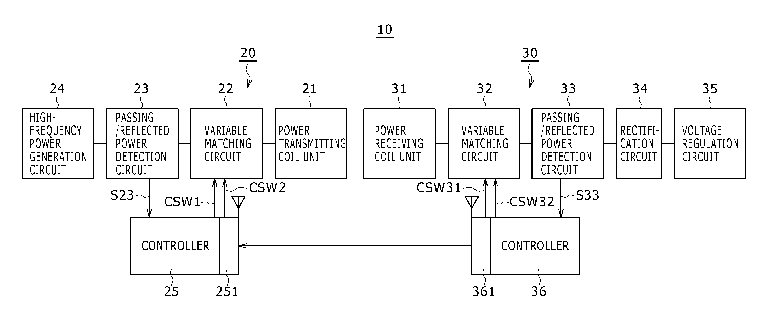
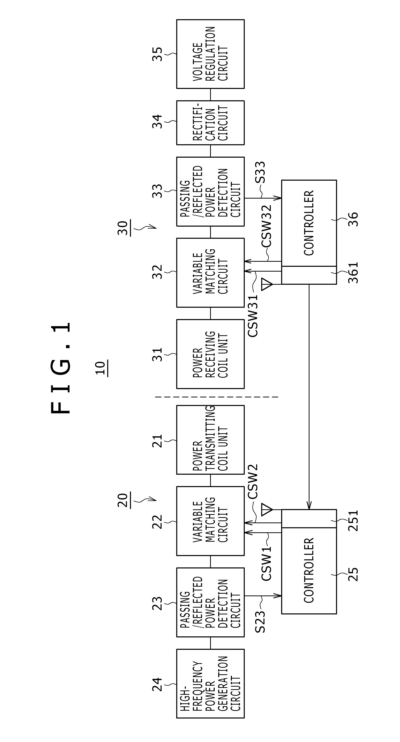
[0035]FIG. 1 is a block diagram showing a configuration example of a wireless power feed system according to the embodiment.

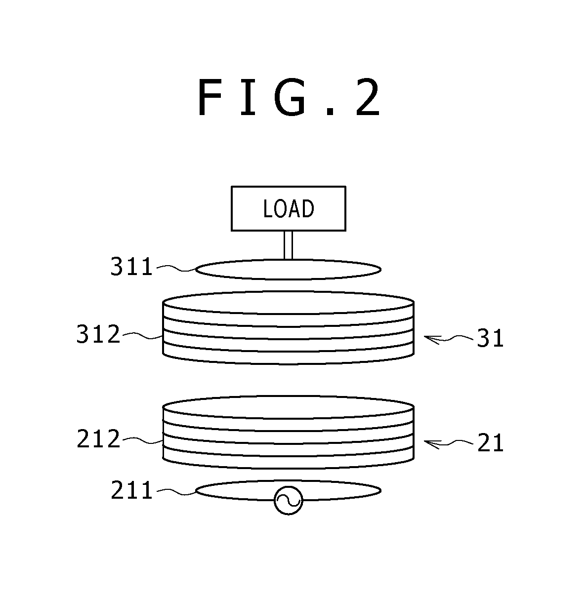
[0036]FIG. 2 is a diagram schematically showing the relationship between coils on the power transmitting side and coils on the power receiving side in the wireless power feed system according to the embodiment.

[0037]This wireless power feed system 10 has a power feed device 20 and a power receiving device 30.

[0038]The power feed device 20 includes a power transmitting coil unit 21, a variable matching circuit 22, a passing / reflected power detection circuit 23, a h...


PUM

PropertyMeasurementUnit
diameteraaaaaaaaaa
diameteraaaaaaaaaa
diameteraaaaaaaaaa

Abstract

A power feed device includes: a power generator configured to generate power that should be fed; a power feed element configured to be formed of a coil fed with power generated by the power generator; a resonance element configured to be coupled to the power feed element by electromagnetic induction; and a variable matching unit configured to include a function for impedance matching at a point of feed of the power to the power feed element, wherein a diameter of the power feed element is changeable, and the variable matching unit is capable of changing the diameter of the power feed element.

Description

BACKGROUND OF THE INVENTION[0001]1. Field of the Invention[0002]The present invention relates to a power feed device, a power receiving device, and a wireless power feed system based on a non-contact power feed system for non-contact (wireless) supply and reception of power.[0003]2. Description of the Related Art[0004]An electromagnetic induction system is known as a system for wireless supply of power.[0005]Furthermore, in recent years, wireless power feed and charge systems employing a system called the magnetic field resonance system based on an electromagnetic resonance phenomenon are attracting attention.[0006]Presently, in the non-contact power feed system based on the electromagnetic induction system, which has been already widely used, the power feed source and the power feed target (power receiving side) need to share magnetic flux. Therefore, the power feed source and the power feed target need to be disposed extremely close to each other for power sending with high effici...

Claims


Application Information

Patent Timeline
Patent Type & Authority Applications(United States)
IPC IPC(8): H01F38/14H01Q7/00H01Q9/14H04B5/48
CPCH02J5/005H01F27/2871H01F38/14H02J50/12
Inventor KOZAKAI, OSAMU
Owner SONY CORP
Learn More