
Numerical control device

Inactive Publication Date: 2011-07-07
SHINNIPPON KOKI
View PDF24 Cites 45 Cited by
  • Summary
  • Abstract
  • Description
  • Claims
  • Application Information

AI Technical Summary

Benefits of technology

[0015]It is an object of the invention to provide a numerical control device resolving the above-described problems.
[0016]In order to attain the above-described object, the numerical control device according to the invention controls a machine tool having at least a spindle for mounting a tool, a spindle head that fixedly holds the spindle, a machine table on which a machining object is fixedly disposed, the relative positional relationship between the spindle head and the machine table including a rotation posture being controlled about a plurality of axes for driving, and motors adapted for drive about each of axes, with a preparatory reference coordinate system, in which orientations of coordinate axes and a position of an original point are fixed, being set on the machine table, the numerical control device having a preparation unit, a first control unit, a second control unit, and a third control unit; wherein the preparation unit has at least an NC program management unit, a preparatory information management unit, and a tool information management unit as segmentalized sub-means; the NC program management unit stores in a preparation information memory unit a NC program having described therein a trajectory of a tool position, which is a position including a tool posture in a program coordinate system fixed to the machining object, a tool path formed of a tool feed speed command indicating a feed speed thereof, and an as-needed tool path correction command; the preparatory information management unit stores in the preparation information memory unit preparatory information, which is information on a position that is in the preparatory reference coordinate system and composed of original point coordinate in the program coordinate system and posture angles indicating orientations of coordinate axis cosines, as an arrangement position including a posture of the machining object to the machine table; the tool information management unit stores in the preparation information memory unit tool information including a shape of the tool used, a length of the tool, and dimensional information on a correction amount of a tool radius; the first control unit has as segmentalized sub-mea

Problems solved by technology

Therefore, changes corresponding to an axis configuration are unavoidable in each control process.
As a result, a plurality of functions are entangled and complexity is increased.
Further portions of the control processes relating to the configuration of axes should be extracted and converted to a black box, each control process should be simplified, and each control process should be facilitated by making common as many portions of the control processes as possible, but the extraction of portions relating to the configuration of axes is incomplete and the conversion to a black box is impossible.
As a result, the software greatly increases in size and complexity and the development time and maintenance time are increased.
Accordingly, the problem is to create a numerical control that can be used as is even when a tool length changes.
However, this approach cannot be directly applied to a five-axis machine tool of a table rotation type that has a rotating axis that rotates the table.
This is because the work rotates as the table rotates and therefore a parallel relationship of the coordinate system of the work and the XYZ coordinate axes of the machine tool is lost.
However, in these tool tip control functions, the commands are different and important issues relating to usage are also different.
However, numerical control of parallel mechanism machine tools actually tends to be difficult and is handled in a special way.
The description of Japanese Patent Application Publication No. 2001-92508 shows that each time a control of a parallel mechanism machine tool is developed, it is a time-consuming procedure.
Such a system is effective in the case of an inherently smooth curve such as a circular arc, but is not necessarily effective in applications to a NC program that describes a movement trajectory of a tool by a set of short linear command blocks that are typically used.
H11-149306 is randomly produced on the original polygonal line since a tool path is bent on the boundaries of blocks, and therefore subsequent smooth polynomial interpolation is impossible.
Further, a method of changing the tool path into a smooth curve that is called “nano-smoothing” has also been suggested, but the conditions under which the tool path can be smoothly changed by nano-smoothing are limited.
For example, the conversion into a curve is impossible between the points in which angular deflection of the orientation of an advance direction vector of the tool path is too large.
Therefore, when the control is performed on the basis of a NC program including sets of short linear blocks, which are typically used, it is impossible not to use the B acceleration-deceleration.
Where the B acceleration / deceleration is used, the internal rotation error is generated in a smooth movement such as circular arc interpolation.
However, when the Z-axis and the W-axis are used simultaneously, various limitations are involved.
Thus, other functions cannot be used, for example, tool diameter correction and circular arc interpolation cannot be used.

Method used


Image

  • Numerical control device
  • Numerical control device
  • Numerical control device

Examples


Embodiment Construction

[0042]Embodiments of the present invention will be described below with reference to the appended drawings.

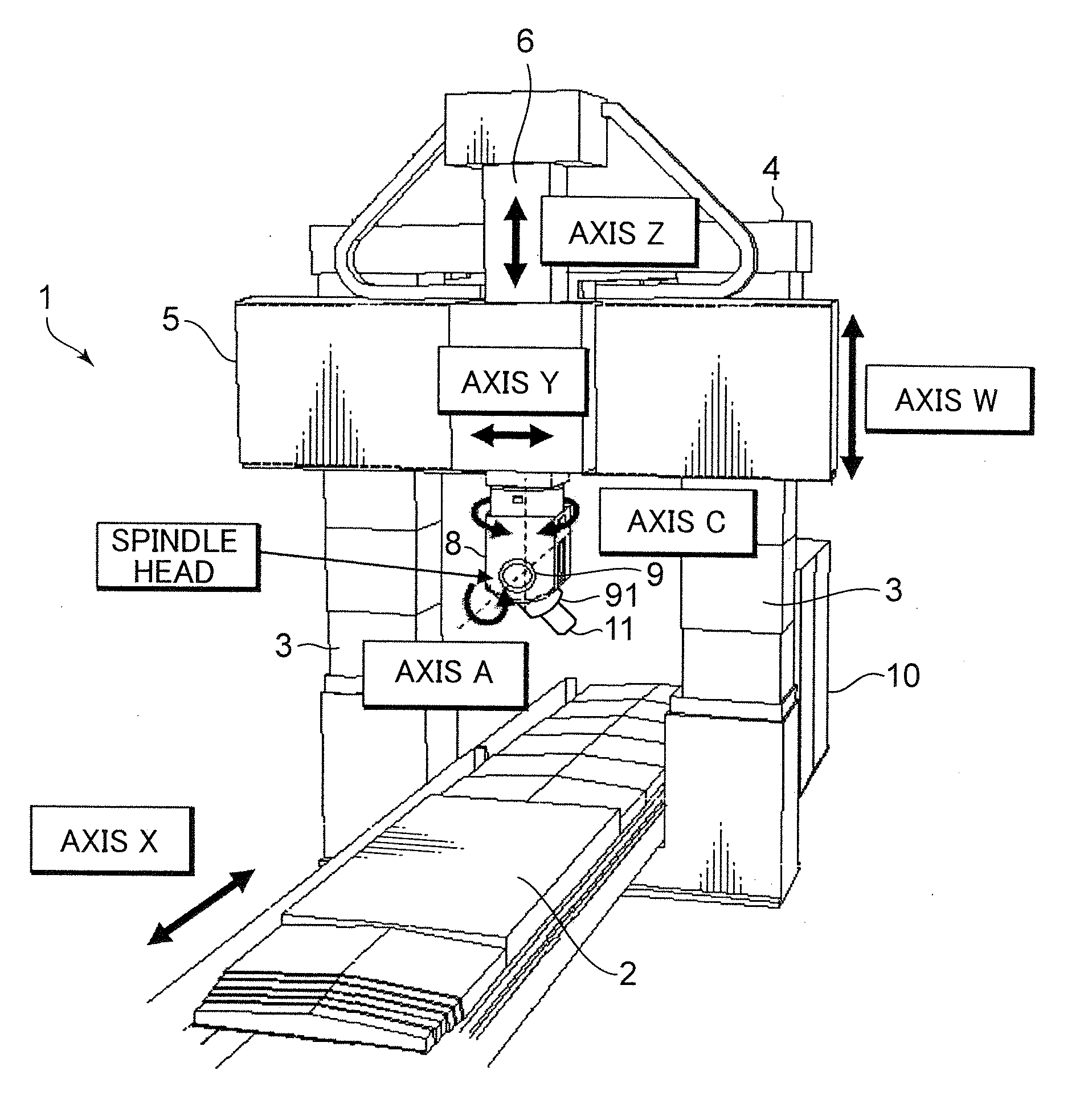
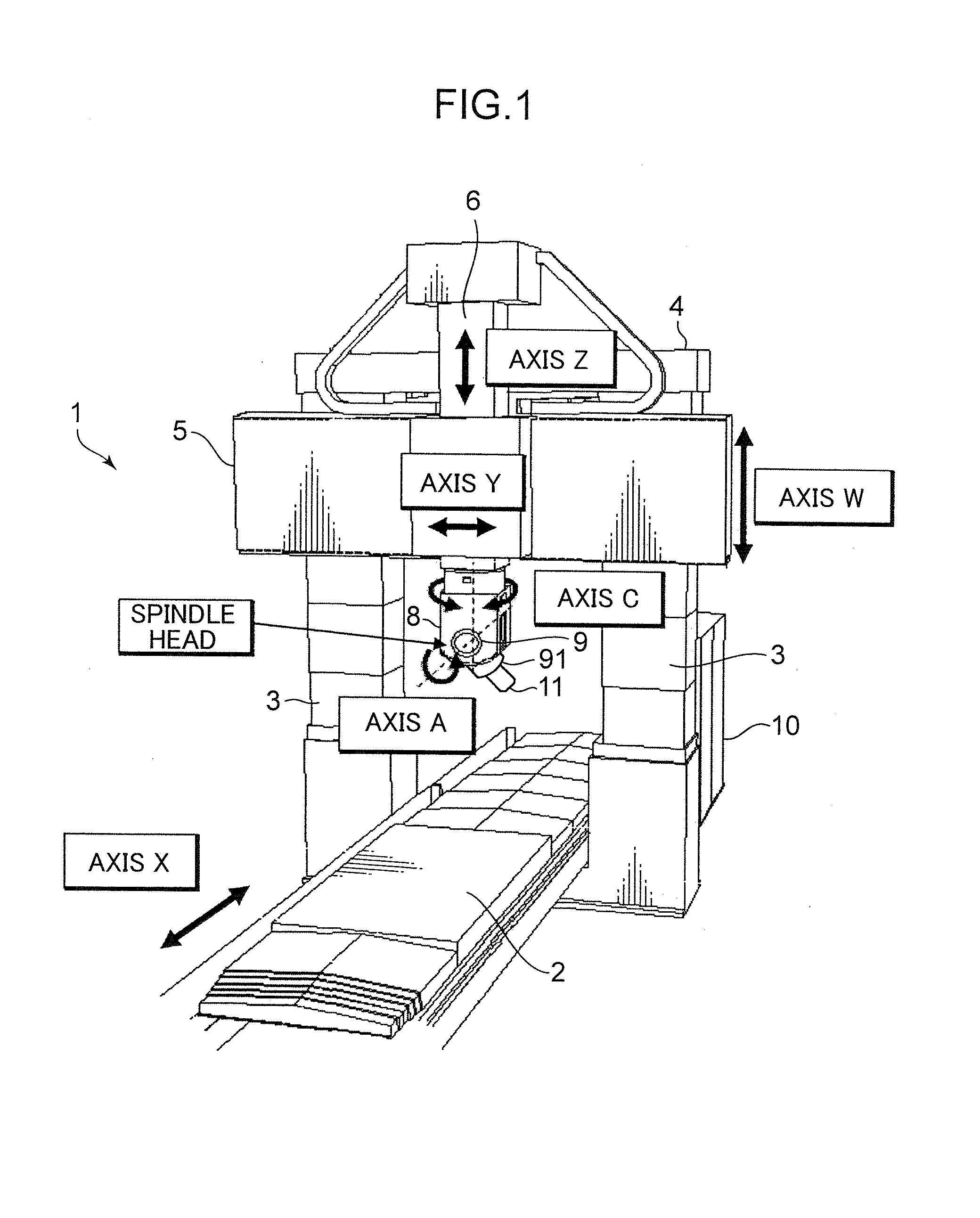
[0043]FIG. 1 is a perspective view showing the entire five-axis machine tool as an example of a machine tool to which the present invention is applied. Referring to FIG. 1, a machine tool 1 has a machine table 2 holding a work as a machining object. The machine table 2 has a front-rear arrangement in the longitudinal direction and configured to be movable in the direction of X-axis for driving (horizontal front-rear direction). A pair of support columns 3, 3 having a ball screw portion (not shown in the figure) are installed vertically on both sides in the intermediate location of the machine table 2, and a beam 4 is spanned between the upper end portions of the support columns 3, 3. A motor MO (see FIG. 14) is disposed as a drive source inside the beam 4. The ball screw portions of the left and right support columns 3, 3 are synchronized via a bevel gear (not shown in the figu...


PUM


Abstract

A main control process is made common to all machine tools by describing in a NC program a tool trajectory including a change in posture in a coordinate system (30) fixed to a machining object (W), fixedly arranging a preparatory reference coordinate system (20) on a machine table (2), representing an installation position of the machining object (W) and a position of a spindle (91) on which a tool (11) is mounted in the preparatory reference coordinate system (20), and containing portions relating to a configuration of axes in a conversion function group of correlation between the position (q) of the spindle (91) and an axis coordinate (r). Thus, the processes of reading the NC program, correction of the tool trajectory and conversion into the trajectory of a spindle position based on the installation position of the machining object, the tool shape, and tool dimensions are made completely common.

Description

BACKGROUND OF THE INVENTION[0001]1. Field of the Invention[0002]The present invention relates to a software structuring technique and an acceleration / deceleration control technique by which practically the entire control software is made to be common to all machine tools in numerical control of machine tools in any mechanical structure such as parallel mechanism machine tools and five-axis machine tools of various forms.[0003]2. Description of the Prior Art[0004]Machine tools of different kinds are known, and the control systems thereof are established by configurations of axes driven by motors. The configurations of axes differ between the machine tools such as a simultaneous two-axis control lathe, a simultaneous three-axis control machining center, a head-side rotation-type five-axis machine tool, a table rotation five-axis machine tool, a mixed mode five-axis machine tool, and a parallel mechanism machine tool.[0005]In such various machine tools, a program coordinate system is d...

Claims


Application Information

Patent Timeline
IPC IPC(8): G05B19/19G05B19/404
CPCG05B2219/36504G05B19/4103G05B19/416G05B2219/50162G05B19/4086G05B19/414G05B2219/50165G05B2219/33271G05B2219/34202G05B2219/36231G05B2219/41405G05B2219/49121G05B2219/33269
Inventor NISHIBASHI, NOBUTAKA
Owner SHINNIPPON KOKI
Learn More