
Radar apparatus, antenna apparatus, and data acquisition method

a technology for antennas and radars, applied in direction finders using radio waves, multi-channel direction-finding systems using radio waves, instruments, etc., can solve the problems of limited increased total increased so as to reduce the size of radar apparatus, efficiently transmit/receive signals, and high angular resolution

Inactive Publication Date: 2011-07-07
HL MANDO CORP
View PDF45 Cites 21 Cited by
  • Summary
  • Abstract
  • Description
  • Claims
  • Application Information

AI Technical Summary

Benefits of technology

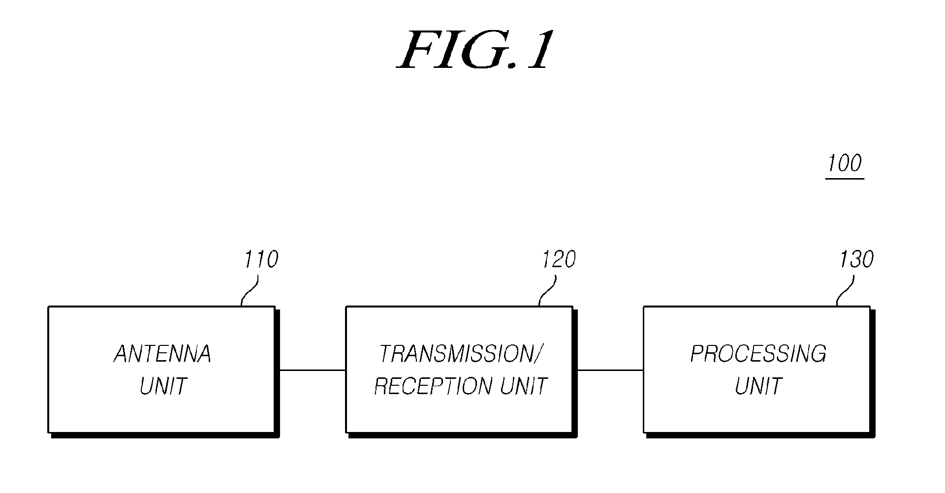
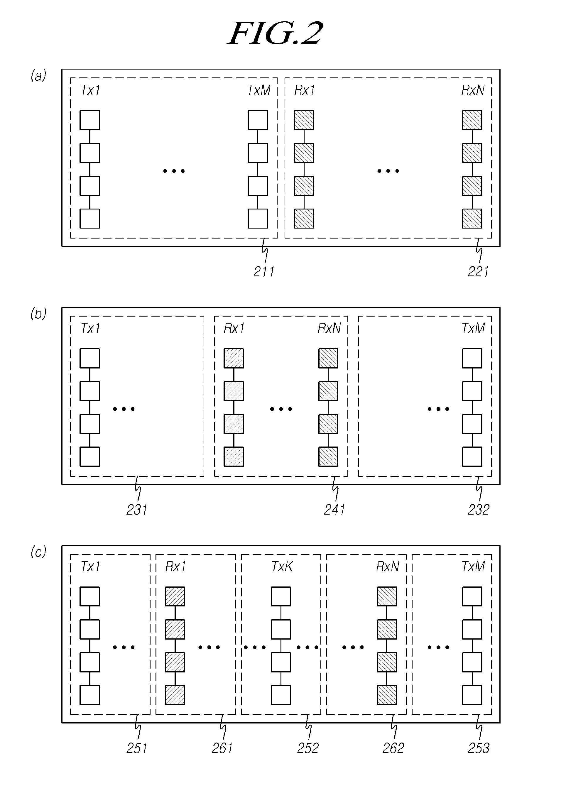
[0009]Accordingly, the present invention has been made to solve the above-mentioned problems occurring in the prior art, and an object of the present invention is to provide an antenna structure which can reduce the size of a radar apparatus while maintaining high angular resolution and a radar apparatus design technology that can efficiently transmit / receive signals using such an antenna structure.
[0014]As described above, according to an embodiment of the present invention, an antenna structure which can reduce the size of a radar apparatus while maintaining high angular resolution and a radar apparatus design technology that can efficiently transmit / receive signals using such an antenna structure can be provided.

Problems solved by technology

The radar apparatus in the related art that has a structure in which several receiving antennas are arranged has the problem that the whole size of the radar apparatus is increased since the size of the antenna structure is increased and many elements related to a transmission / reception unit (that is, RF circuit unit) are required.
However, at present, when mounting a radar apparatus on a vehicle, a portion on which the radar apparatus can be mounted is limited due to various kinds of structures, such as an ultrasonic sensor in a bumper, a vehicle license plate, mist lights, support structures, and the like, and thus the size of the radar apparatus should be limited.
Accordingly, development of a radar apparatus that can reduce the size of the radar apparatus as well as maintaining high angular resolution is required, but the radar apparatus in the related art cannot satisfy such requirements.

Method used


Image

  • Radar apparatus, antenna apparatus, and data acquisition method
  • Radar apparatus, antenna apparatus, and data acquisition method
  • Radar apparatus, antenna apparatus, and data acquisition method

Examples


Embodiment Construction

[0028]Hereinafter, exemplary embodiments of the present invention will be described with reference to the accompanying drawings. In the following description, the same elements will be designated by the same reference numerals although they are shown in different drawings. Further, in the following description of the present invention, a detailed description of known functions and configurations incorporated herein will be omitted when it may make the subject matter of the present invention rather unclear.

[0029]In addition, terms, such as first, second, A, B, (a), (b) or the like may be used herein when describing components of the present invention. Each of these terminologies is not used to define an essence, order or sequence of a corresponding component but used merely to distinguish the corresponding component from other component(s). It should be noted that if it is described in the specification that one component is “connected,”“coupled” or “joined” to another component, a t...


PUM


Abstract

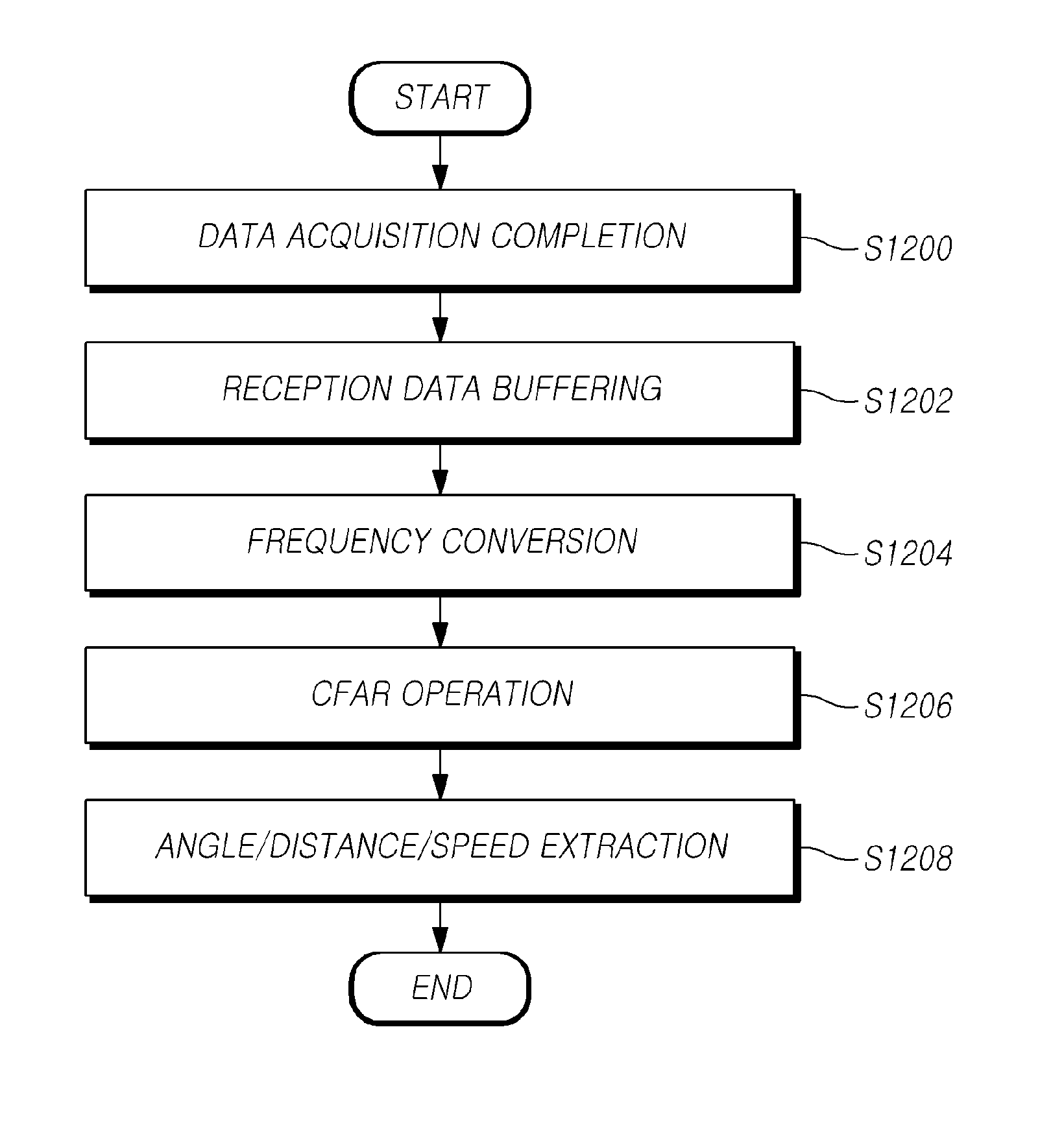
A radar apparatus, an antenna apparatus, and a data acquisition method are provided, which can reduce the size of a radar apparatus as well as maintaining angular resolution.

Description

CROSS-REFERENCE TO RELATED APPLICATION[0001]This application claims priority from and the benefit under 35 U.S.C. §19(a) of Korean Patent Application No. 10-2010-0000338, filed on Jan. 5, 2010, which is hereby incorporated by reference for all purposes as if fully set forth herein.BACKGROUND OF THE INVENTION[0002]1. Field of the Invention[0003]The present invention relates to a radar apparatus, an antenna apparatus, and a data acquisition method, and more particularly to a technology that can reduce the size of a radar apparatus as well as maintaining angular resolution.[0004]2. Description of the Prior Art[0005]As generally known in the art, a radar apparatus mounted on a vehicle or the like must have high angular resolution. For example, in the case of a vehicle radar for preventing forward collision, during in-path cut in and cut out of a vehicle in a front neighboring lane, a cut in situation can be judged through an angle extraction. That is, through a high angular resolution c...

Claims


Application Information

Patent Timeline
IPC IPC(8): G01S13/04G01S13/00G01S13/931
CPCG01S3/74G01S7/03G01S13/422H01Q21/061H01Q1/3233H01Q1/3283H01Q21/0006G01S13/931
Inventor YANG, JOO YEOLLEE, JAE EUNSONG, KYEONG JINJEONG, SEONG HEECHOI, SEUNG UNHAM, HYUNG SUK
Owner HL MANDO CORP
Learn More