
Battery pack, charging apparatus, and charging system

a battery pack and charging apparatus technology, applied in secondary cells, cell components, instruments, etc., can solve the problems of complex circuit structure and complex circuit structure, and achieve the effect of prolonging the life of the battery pack and suppressing unnecessary power consumption

Inactive Publication Date: 2011-07-07
SONY CORP
View PDF6 Cites 2 Cited by
  • Summary
  • Abstract
  • Description
  • Claims
  • Application Information

AI Technical Summary

Benefits of technology

A charging apparatus has a charging circuit that charges a battery pack and a control circuit that controls the charging, so its circuit structure is complex. When a charge amount selecting switch is included, therefore, the circuit structure becomes more complex.
It is desirable to suppress unnecessary power consumption and prolong the life of a battery pack without having to make a charging apparatus structure complex.
Accordingly, a charge selecting means for selecting a desired amount of charge can be eliminated from the charging apparatus, so it is possible to suppress unnecessary power consumption and prolong the life of the battery pack without having to make the charging apparatus structure complex.

Problems solved by technology

A charging apparatus has a charging circuit that charges a battery pack and a control circuit that controls the charging, so its circuit structure is complex.
When a charge amount selecting switch is included, therefore, the circuit structure becomes more complex.

Method used


Image

  • Battery pack, charging apparatus, and charging system
  • Battery pack, charging apparatus, and charging system
  • Battery pack, charging apparatus, and charging system

Examples


Embodiment Construction

A charging system according to an embodiment of the present invention will be described below.

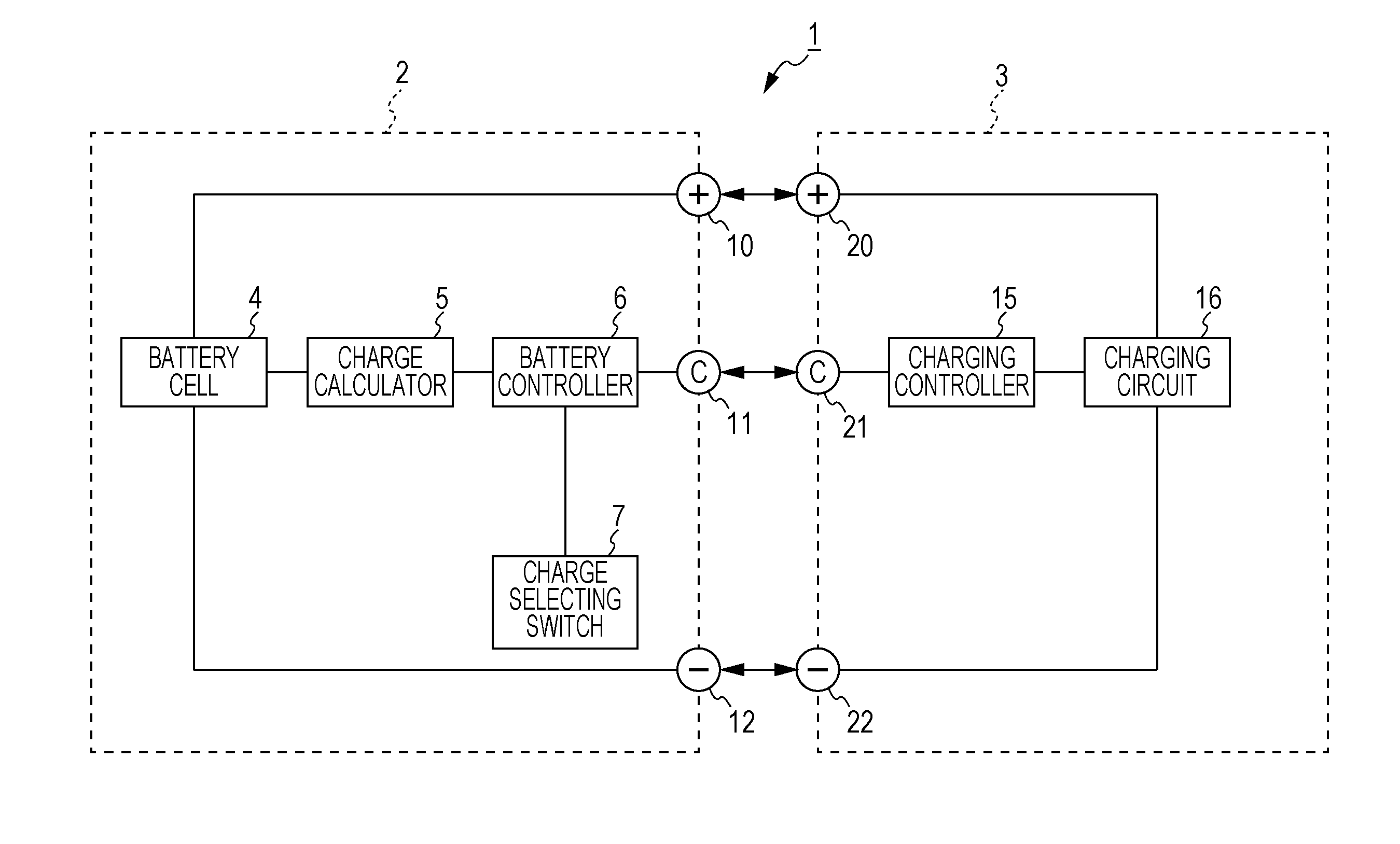
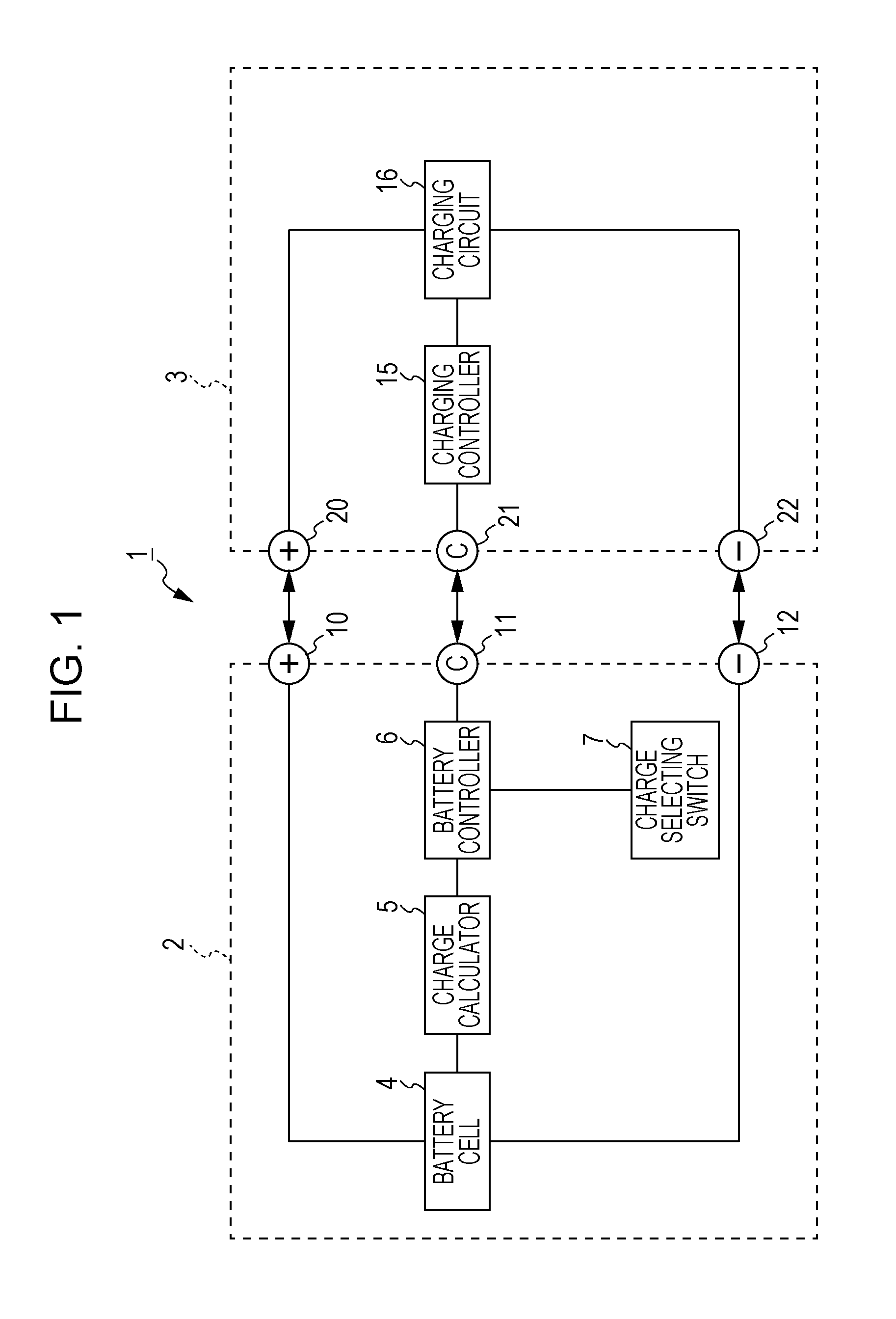
A charging system 1 has a battery pack 2 and a charging apparatus 3 that charges the battery pack 2, as shown in FIG. 1.

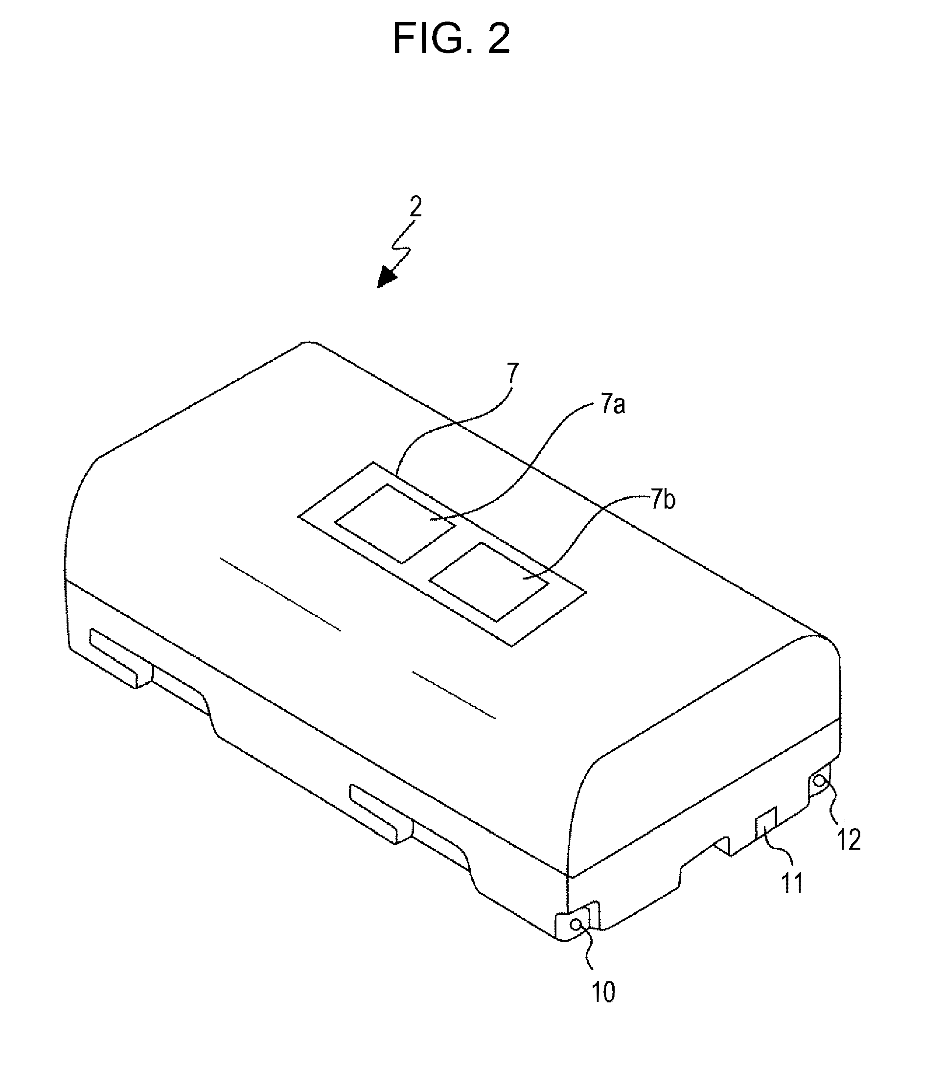
The battery pack 2 has a battery cell 4, a charge calculator 5, a battery controller 6, a charge selecting switch 7, a positive terminal 10, a communication terminal 11, and a negative terminal 12. The battery pack 2 is structured so that it is detachably attached to the charging apparatus 3. A plurality of amounts of charge with different upper limits has been set for the battery pack 2.

The charge calculator 5 detects a charge current to and a discharge current from the battery cell 4, calculates the current amount of charge of the battery cell 4 from the detected currents, and sends calculated charge information to the battery controller 6.

The battery controller 6 controls the charge calculator 5 and charge selecting switch 7, receives the charge information from the cha...


PUM


Abstract

A battery pack includes a battery cell, a charge calculator that calculates an amount of charge of the battery cell, a charge setting that sets multiple amounts of charge with different upper limits, a charge selecting switch that selects one of the amounts of charge, and a battery controller having a communication function that sends, to the charging apparatus, charge information about the battery cell and charging command information that instructs charging to be continued to an upper limit for the selected amount of charge.

Description

BACKGROUND OF THE INVENTION1. Field of the InventionThe present invention relates to a battery pack which can be charged to a plurality of selectable amounts with different upper limits, and to a charging apparatus and a charging system that charge the battery cell in the battery pack.2. Description of the Related ArtA battery pack used for, for example, photography with an electronic device, such as an imaging apparatus, is generally charged until the battery pack is charged to 100% (fully charged). However, a full charge may be unnecessary depending on the photography time taken by the user or the application in which the battery pack is used, and thereby about a half of the full charge, for example, may be adequate. If the battery pack is fully charged in this situation, the remaining charge is released by, for example, a dark current, consuming unnecessary power.In general, in view of battery capacity deterioration, when a battery pack is charged to less than 100%, 80% for examp...

Claims


Application Information

Patent Timeline
Patent Type & Authority Applications(United States)
IPC IPC(8): H02J7/04G01R31/36H02J7/02
CPCH02J7/008H02J7/0004H02J7/00036H02J7/00047H02J7/0048H02J7/00714H01M50/572H01M10/44H01M10/425
Inventor NAGASHIMA, OSAMUMIYAJIMA, YOICHISHINTANI, SHOICHIMORIYA, JIRO
Owner SONY CORP
Learn More