
Ear piece and earphone

a technology of earpiece and earphone, which is applied in the manufacture/assembly of earpiece/earphone, instruments, stethoscopes, etc., can solve the problems of filter member falling off or being detached, and achieve the effect of excellent assembly workability in assembly

Active Publication Date: 2011-06-30
JVC KENWOOD CORP A CORP OF JAPAN
View PDF3 Cites 12 Cited by
  • Summary
  • Abstract
  • Description
  • Claims
  • Application Information

AI Technical Summary

Benefits of technology

[0013]A purpose of the present invention is to provide an ear piece equipped with a filter unit attached to a speaker unit that is installed in a sound tube portion or attached to the top of the sound tube portion, for sound characteristics adjustments and protection of the speaker unit from a foreign body such as earwax, the filter unit being not detached when the ear piece is attached to the sound tube portion, thus exhibiting excellent assembly workability in assembly, and to provide an earphone equipped with such an ear piece.

Problems solved by technology

The earphone disclosed in the document 1 and equipped with a rubber-made ear piece is disadvantageous in that the filter member could be fallen off or detached if a double-sided tape cannot exhibit a high adhesion force under a low-temperature environment, due to the attachment of dust to the surface of the filter member or the ear piece to be bonded, etc.

Method used


Image

  • Ear piece and earphone
  • Ear piece and earphone
  • Ear piece and earphone

Examples


Embodiment Construction

[0026]A preferred embodiment according to the present invention will be described with reference to the attached drawings.

[0027]FIG. 1 shows is an external perspective view of an earphone 50, an embodiment of the present invention.

[0028]The earphone 50, a top mount type, is equipped with: a box-like hosing 1; a main body 2 having the hosing 1; a sound tube portion 3 protruding from the hosing 1; a bushing 4 extending outwardly from the housing 1; and a cord 5 running from the housing 1 through the bushing 4.

[0029]Detachably attached to the top of the sound tube portion 3 is an ear piece 6 made of a flexible material such as silicon rubber.

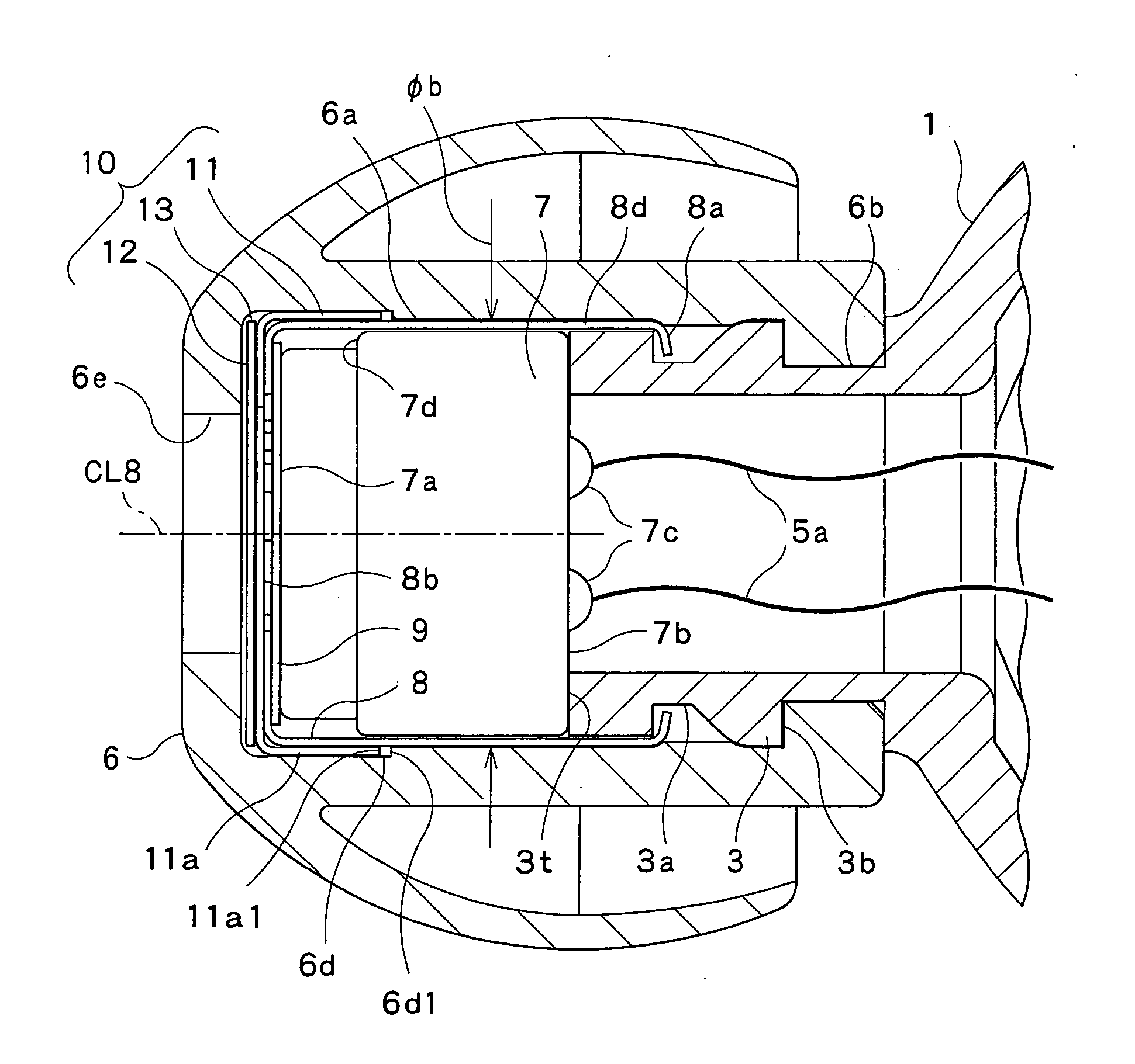
[0030]Attached to the top of the sound tube portion 3 and covered by the ear piece 6 is a speaker unit 7, indicated by a broken line, that converts audio signals externally supplied through the cord 5 into sounds and gives off the sounds.

[0031]As shown in FIG. 1, in the top mount type, the speaker unit 7 is attached to the top of the sound tube por...


PUM


Abstract

An ear piece to be detachably attached to a sound tube protruding from a housing of an earphone has a base portion with a through hole. The through hole has an inner wall with a first, a second, and a third portion continuously provided in order when viewed from the housing. The first portion protrudes inwardly and has a first distance from a protruding inner surface of the first portion to an axis line passing through the cross section of the base portion and the through hole. The second portion has a circumferential inner surface having a second distance longer than the first distance to the axis line. The third portion is formed continuously with the second portion, having a circumferential inner surface with a third distance longer than the second distance to the axis line.

Description

CROSS-REFERENCE TO RELATED APPLICATIONS[0001]This application is based on and claims the benefit of priority from the prior Japanese Patent Application No. 2009-294483 filed on Dec. 25, 2009 and No. 2010-279053 filed on Dec. 15, 2010, the entire contents of which are incorporated herein by reference.BACKGROUND OF THE INVENTION[0002]The present invention relates to an ear piece and an earphone. Specifically, this invention relates to an ear piece attached to a sound tube that protrudes from an earphone body and inserted into the ear channel of a user's ear with the sound tube, and to an earphone to which the ear piece is attached.[0003]One popular earphone is a so-called canal type in which an ear piece is detachably attached to a sound tube that protrudes from an earphone body and is inserted into the ear channel of a user's ear with the sound tube.[0004]The canal type earphone is divided into a type in which a speaker unit is installed in an earphone body (referred to as a unit-ins...

Claims


Application Information

Patent Timeline
IPC IPC(8): H04R1/10G10K11/00
CPCH04R1/1016H04R1/12H04R1/1075
Inventor ISHIZAKA, KAZUNORI
Owner JVC KENWOOD CORP A CORP OF JAPAN
Learn More