Seat

a seat and seat cushion technology, applied in the field of seats, can solve the problems of shifting the load of a sitting person, affecting the comfort of sitting, and the sensor provided in the seat cushion surface portion is apt to be damaged, so as to enhance the strength against the stretching load, facilitate stretching, and increase the durability

Active Publication Date: 2011-06-30
TS TECH CO LTD
View PDF6 Cites 16 Cited by
  • Summary
  • Abstract
  • Description
  • Claims
  • Application Information

AI Technical Summary

Benefits of technology

[0031]In the above configuration, the heater wire in the seat cushion surface portion is disposed so that a wavy shape, i.e., a mountain portion and a valley portion, is continuous. Therefore, when a stretching force acts on the base member in both transverse and longitudinal directions of the vehicle body, the heater wire is also stretched following a stretching deformation of the base member, so that the seat cushion surface portion of the vehicle seat heater can be deformed smoothly in both transverse and longitudinal directions of the vehicle body. Thus, the vehicle seat heater can be deformed smoothly in any of transverse and longitudinal directions of the vehicle body, so even when a transverse load and a longitudinal load with respect to the vehicle body are applied to the vehicle seat, for example when a person gets on the vehicle or while a vehicle is traveling, the vehicle seat heater can be stretched and deformed smoothly as to follow stretching and deformation of the skin material and the cushion member. Generally, in a vehicle seat on which a sitting person moves frequently in the vertical direction due to unevenness of a road surface, for example, a vertical stretching load is especially apt to act on the backrest surface portion of the seat. On the other hand, when the heater wire disposed in the backrest surface portion is disposed in a wavy shape in the vertical direction, the heater wire in the backrest surface portion can be deformed smoothly in the vertical direction and hence high durability against a vertical stretching load is obtained. Also, the heater wires in the seat cushion surface portion and the backrest surface portion may be disposed so that their densities, i.e., heat wire spacing, are different from each other. In the seat cushion surface portion against which the sitting person's hip and legs come into abutment, since a larger vertical load is exerted thereon, it is necessary to narrow the heater wire spacing and thereby enhance the strength against the stretching load. On the other hand, as to the backrest surface portion, since it comes into abutment against the sitting person's waist, there are fewer cases where a large load acts thereon compared to the seat cushion surface portion. Therefore, in the seat cushion surface portion, in order to permit easier stretching against a vertical stretching load, the heater wires are disposed so as to widen their spacing. By thus disposing the heater wires in the seat cushion surface portion and the backrest surface portion so that their extending directions and spaces are different from each other, it is possible to cope with load characteristics dependent on various portions. As a result, it is possible to improve the feeling when a person sits on the vehicle seat, and hence it is possible to not only provide a sitting person with a comfortable feeling but also surely enhance the stretching strength of the vehicle seat heater. Thus, at various portions (seat cushion surface portion, backrest surface portion, connection surface portion, insertion portion) of the vehicle seat heater with different load characteristics respectively, those portions can be stretched in various directions, so that not only the stretching strength of the whole of the vehicle seat heater can be improved, but also it is possible to realize a comfortable ride.
[0032]Preferably, in another embodiment, the cushion member is provided between the seat cushion surface portion and the backrest surface portion with a pulling-over slot for pulling over the base member, the base member further includes a connection surface portion disposed between the seat cushion surface side portion and the backrest surface side portion and attached in a bent state to the pulling-over slot, the heater wire further includes a plurality of connection heater wires connecting the seat cushion surface side heater wire and the backrest surface side heater wire electrically to each other, the connection heater wires being fixed to the connection surface portion, and the heater wire is disposed so that the distance between mutually closest portions of the connection heater wires is larger than the distance between mutually closest portions of the first extend

Problems solved by technology

In such a seat, however, the load of a sitting person shifts frequently while a vehicle is traveling, for example, with a large load being imposed on the seat.
As a result, the sensor provided in the seat cushion surface portion is apt to be damaged.
However, Japanese Patent Application Publication No. 2005-279070 does not describe a configuration related to a temperature control means such as a thermistor.
Therefore, not only does the temperature control means e

Method used


Image

  • Seat
  • Seat
  • Seat

Examples


Embodiment Construction

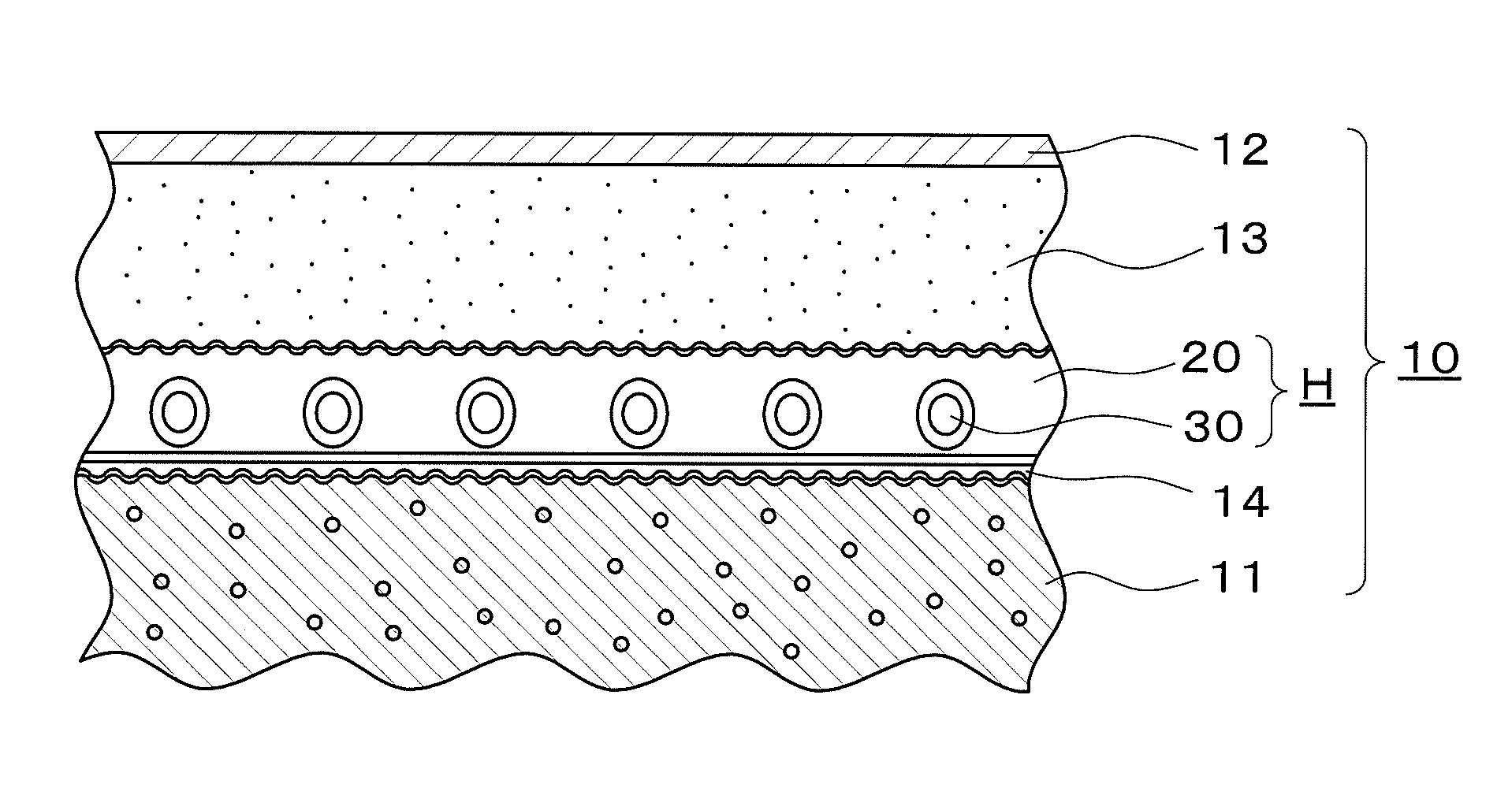
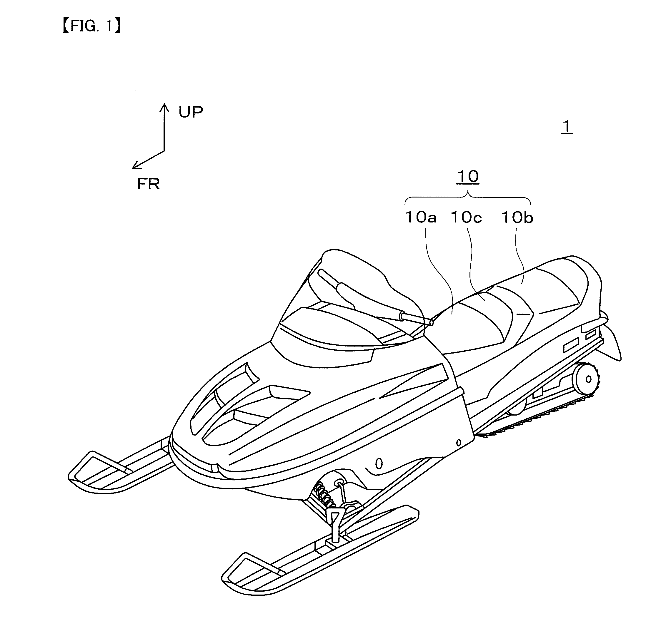
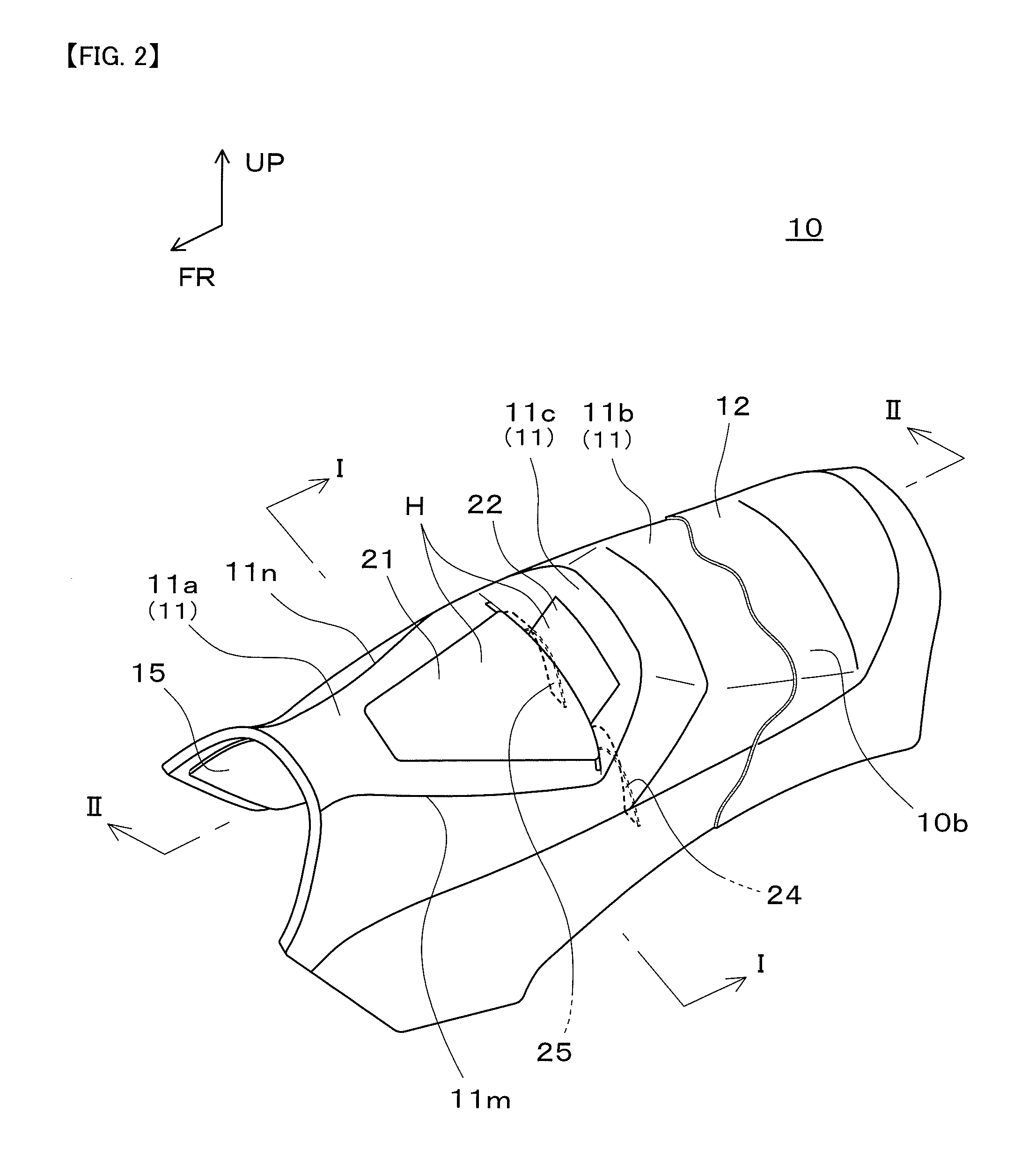
[0046]An embodiment of the present invention will be described below with reference to the drawings. It goes without saying that the members and arrangements to be described do not limit the present invention, but that various modifications may be made in accordance with the gist of the invention. FIGS. 1 to 11 illustrate an embodiment of the present invention, of which FIG. 1 is a perspective view of a vehicle having a seat, FIG. 2 is a perspective view of the seat with a seat heater disposed therein, FIG. 3 is plan view of a cushion member, FIG. 4 is an enlarged sectional view taken on line I-I in FIG. 2, FIG. 5 is a plan view of the seat heater, FIG. 6 is an enlarged sectional view of a principal portion taken on line II-II in FIG. 2, FIG. 7 is a view explanatory of an installed state of a skin material, the cushion member, and a bottom plate, FIG. 8 is a side view showing a state in which the cushion member and the seat heater were placed on the bottom plate, FIG. 9 is a perspec...


PUM


Abstract

A seat comprises a cushion member, a seat heater, and a skin material. The seat heater has a planar base member disposed on the cushion member, a heater wire fixed to the base member, and a temperature control that controls the temperature of the heater wire. The skin material covers both the cushion member and the seat heater. The cushion member includes a seat cushion surface portion for a sitting person and a recess formed in a surface located on the side opposite to the seat cushion surface portion. The base member includes a seat cushion surface-side portion disposed on the seat cushion surface portion. The heater wire includes a seat cushion surface-side heater wire disposed in the seat cushion surface-side portion and an insertion portion heater wire extended from the seat cushion side heater wire. At least a part of the temperature control is connected to the insertion portion heater wire and is disposed within the recess of the cushion member.

Description

BACKGROUND OF THE INVENTION[0001]1. Technical Field[0002]The present disclosure relates to a seat, and more particularly to a seat capable of reducing a load imposed on a temperature control means of a seat heater.[0003]2. Related Art[0004]Heretofore, at a low atmospheric temperature for example in winter, there has been the problem that, when a person sits on a seat, the seat temperature is low and does not feel comfortable. In view of this point, there has been developed a technique of disposing a seat heater in the seat. By disposing a seat heater not only in a seating portion (seat cushion surface portion) against which the hip of a sitting person comes into abutment but also in a backrest surface which bears the waist of the sitting person, the feeling when the person sits thereon is improved.[0005]As noted above, the seat heater is provided, for example, for the retention of heat and for the prevention of freezing. The seat heater is a planar heating unit capable of heating th...

Claims


Application Information

Patent Timeline
IPC IPC(8): B60N2/56
CPCB60N2/5685B62J33/00B62J1/12B60N2/5825
Inventor MATSUSHIMA, MASAAKI
Owner TS TECH CO LTD
Why Eureka
Try Eureka