
Sensor

Active Publication Date: 2011-06-23
LIEBHERR WERK EHINGEN
View PDF5 Cites 38 Cited by
  • Summary
  • Abstract
  • Description
  • Claims
  • Application Information

AI Technical Summary

Benefits of technology

According to an aspect of the present invention, there is provided a sensor which allows substantially smaller tolerance limits.

Problems solved by technology

To cope with the strict demands on safety in the handling of complex machinery, the installation of a component of the machinery may be redundant or diverse.
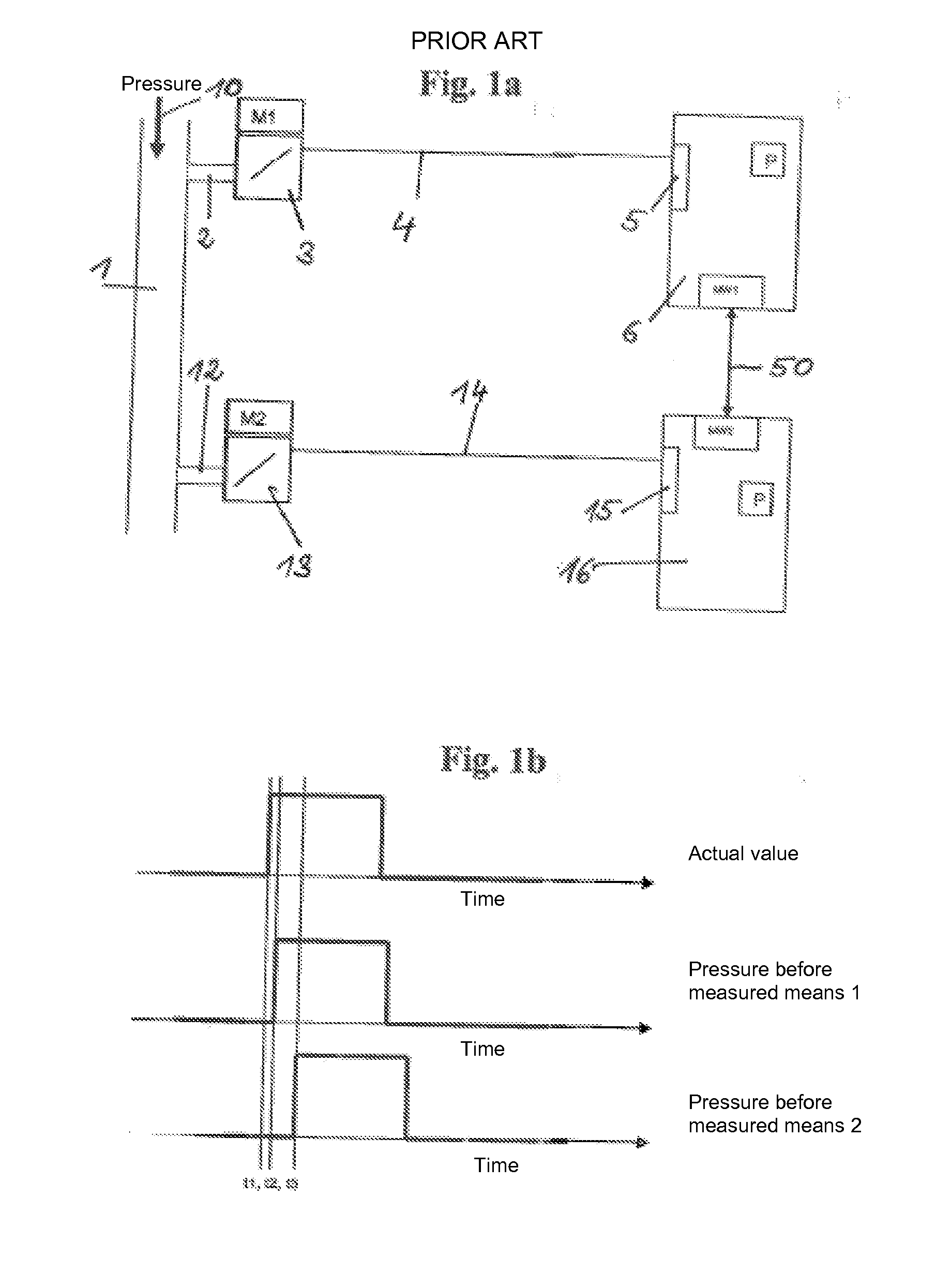
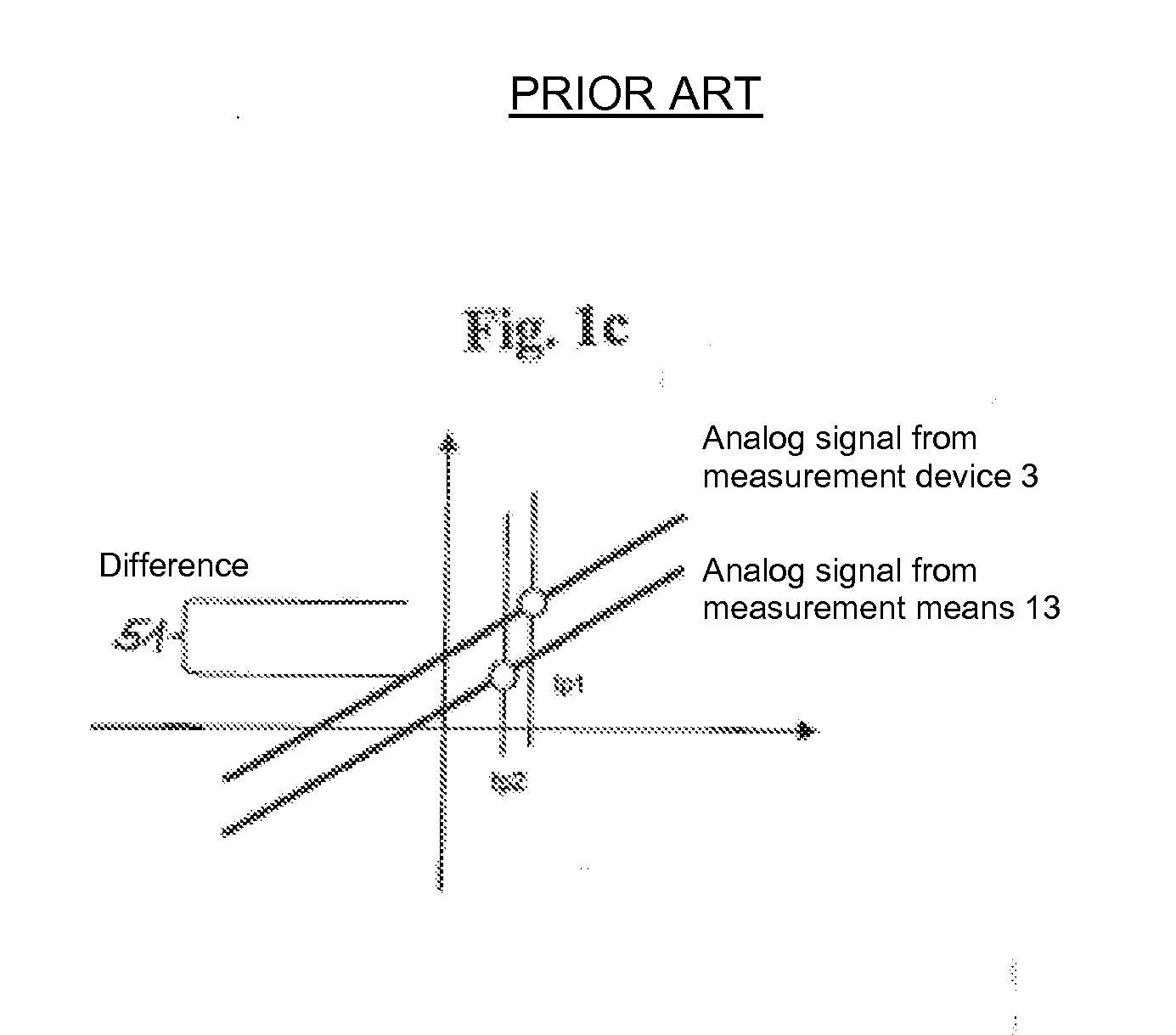
A substantial problem of the conventional sensor arrangement is caused by that the individual measured values MW1 and MW2 generated in dependence on time on the basis of the time difference 51 result in considerable measurement uncertainties.

Method used


Image

  • Sensor
  • Sensor
  • Sensor

Examples


Embodiment Construction

The present invention will now be described more specifically with reference to the following Embodiments. It is to be noted that the following descriptions of preferred Embodiments of this invention are presented herein for purpose of illustration and description only; it is not intended to be exhaustive or to be limited to the precise form disclosed.

According to an embodiment of the present invention, a sensor has at least two measured value pick-ups and at least two processing units within a sensor housing. The measured value pick-up is defined as a part of the sensor which directly responds to a measured variable to be detected. Each measured value pick-up may be connected via a signal line to each processing unit so that the signal value representing the measured value can be transferred to the processing unit.

To increase the reliability or safety of the sensor, both the measured value pick-ups and the processing units are made redundant and / or diverse. The at least two measure...


PUM


Abstract

A sensor for measuring any desired variable, with the sensor having a sensor housing with a specimen feed and with at least two measured value pick-ups and at least two processing units being arranged redundantly respectively pairwise with respect to one another and / or diversely in the sensor housing.

Description

CROSS-REFERENCE TO RELATED APPLICATION AND CLAIM OF PRIORITYThis application claims the benefit of German Utility Model Application No. 20 2009 017 430.1, filed on Dec. 23, 2009, in the German Patent and Trademark Office, the disclosures of which are incorporated herein in their entirety by reference.BACKGROUND1. Field of the InventionThe present invention relates to a sensor for measuring a desired variable.2. Description of the Related ArtTo cope with the strict demands on safety in the handling of complex machinery, the installation of a component of the machinery may be redundant or diverse.In the case of a sensor, since the sensor under certain circumstances takes up relevant measured variables for the safe operation of the machine, redundant sensors may be installed for a proper working of the controller of a machine, particularly in the data transfer from the sensor to the processor. Redundancy may also be necessary in this area to guarantee the demanded safety conditions. A ...

Claims


Application Information

Patent Timeline
IPC IPC(8): G06F15/00
CPCG01D3/08G01D11/245G01D5/24461
Inventor MORATH, ERWIN
Owner LIEBHERR WERK EHINGEN
Learn More