Electronic sphygmomanometer for enhancing reliability of measurement value

Inactive Publication Date: 2011-06-23
OMRON HEALTHCARE CO LTD
View PDF3 Cites 13 Cited by
  • Summary
  • Abstract
  • Description
  • Claims
  • Application Information

AI Technical Summary

Benefits of technology

[0039]According to one or more embodiments of the present invention, the reliability of the blood pressure measurement value can be enhanced since the blood pressure measurement and the detection of abnormality on the plurality of pressure sensors can be carried out based on the cuff pressures detected using the plurality of pressure sensors.

Problems solved by technology

Thus, even if the output of the pressure sensor, which is the most important in the blood pressure measurement, is shifted by greater than or equal to a defined allowable tolerance, there is no method of noticing such a phenomenon and it is unknown whether of not the blood pressure measurement value is correct.
Thus, even if the blood pressure measurement value greatly differs from the normal blood pressure or the casual blood pressure, it is unknown whether the measurement value is really different from the blood pressure value or is different due to an error of the pressure sensor of the sphygmomanometer, which may cause a user to feel anxious.
Specifically, abnormality is detected when the detected pressure value of the pressure sensor greatly exceeds 300 mmHg, for example.
Therefore, the other pressure sensor is applied for safety countermeasures defined in the medical standard IEC 60601-2-30, and does not guarantee the accuracy of one of the pressure sensors used for the blood pressure measurement.
To this end, an expensive pressure sensor needs to be used since required is a highly accurate pressure sensor that is not influenced by disturbance such as temperature changes and that has small change over the years.
Furthermore, as the two pressure sensors having the functions for the different purposes are mounted, the failure rate of the sphygmomanometer due to the failures of the pressure sensors simply doubles compared to a sphygmomanometer with one pressure sensor.

Method used


Image

  • Electronic sphygmomanometer for enhancing reliability of measurement value
  • Electronic sphygmomanometer for enhancing reliability of measurement value
  • Electronic sphygmomanometer for enhancing reliability of measurement value

Examples


first embodiment

[0061]An electronic sphygmomanometer mounted with two pressure sensors according to a first embodiment of the invention will be described. The measurement site is assumed to be an upper arm. The electronic sphygmomanometer calculates the blood pressure in accordance with the oscillometric method. The method applied to calculate the blood pressure is not limited to the oscillometric method.

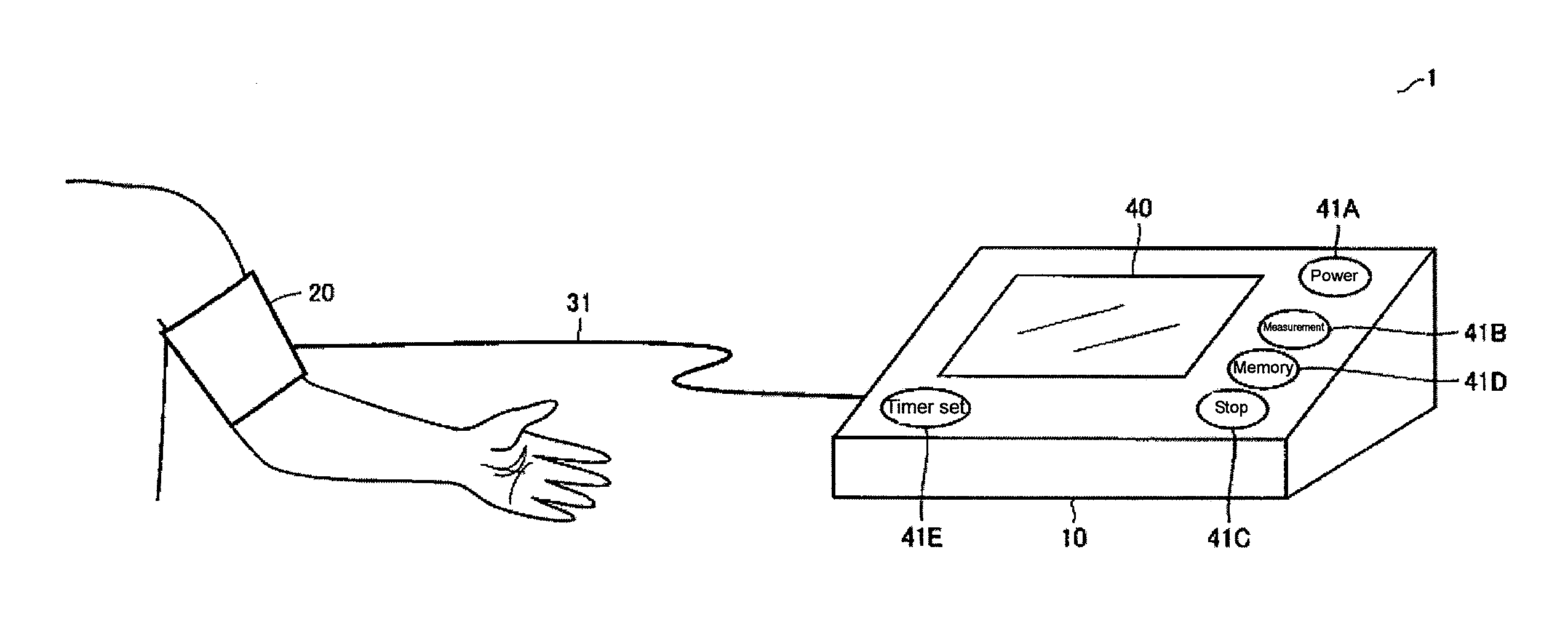
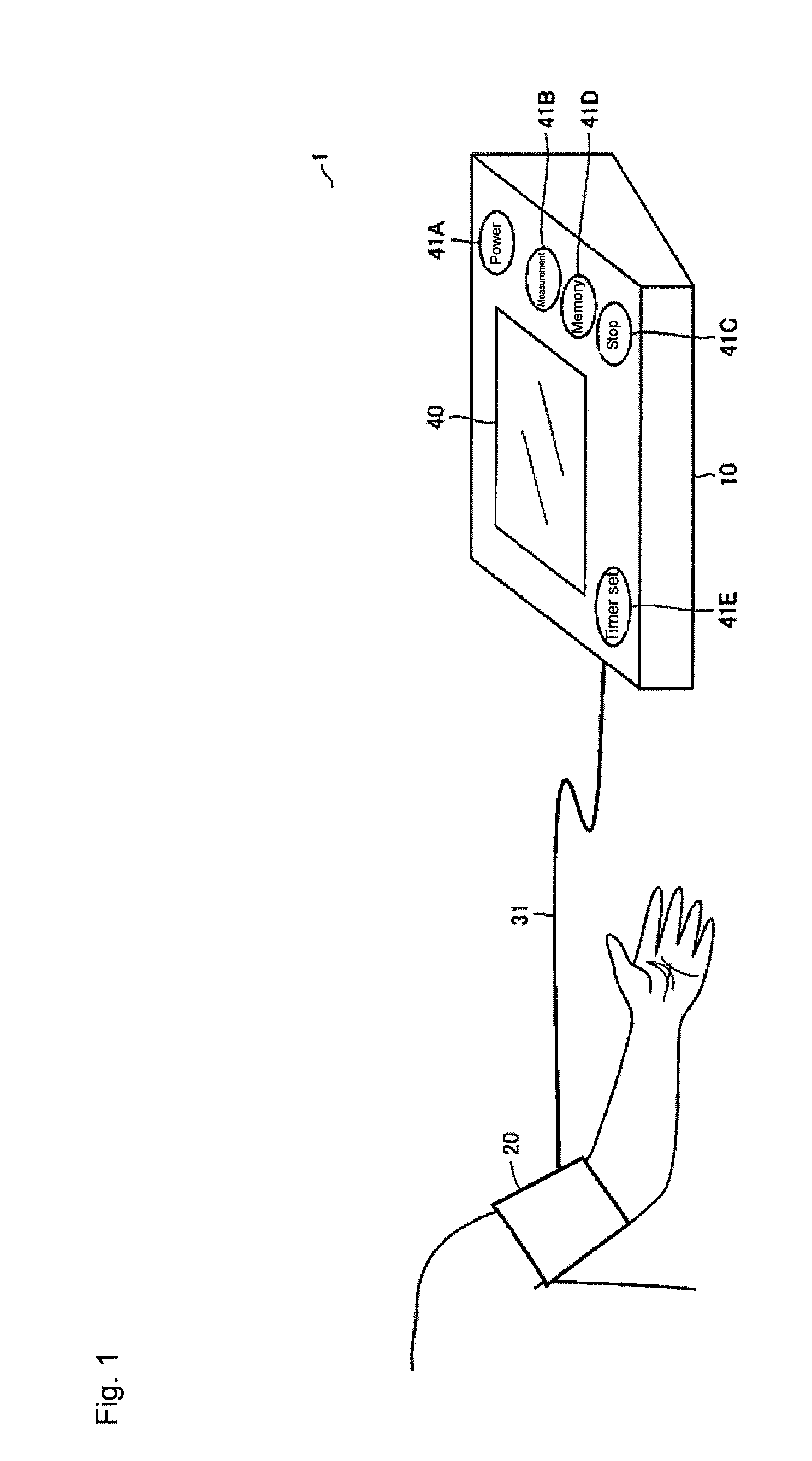
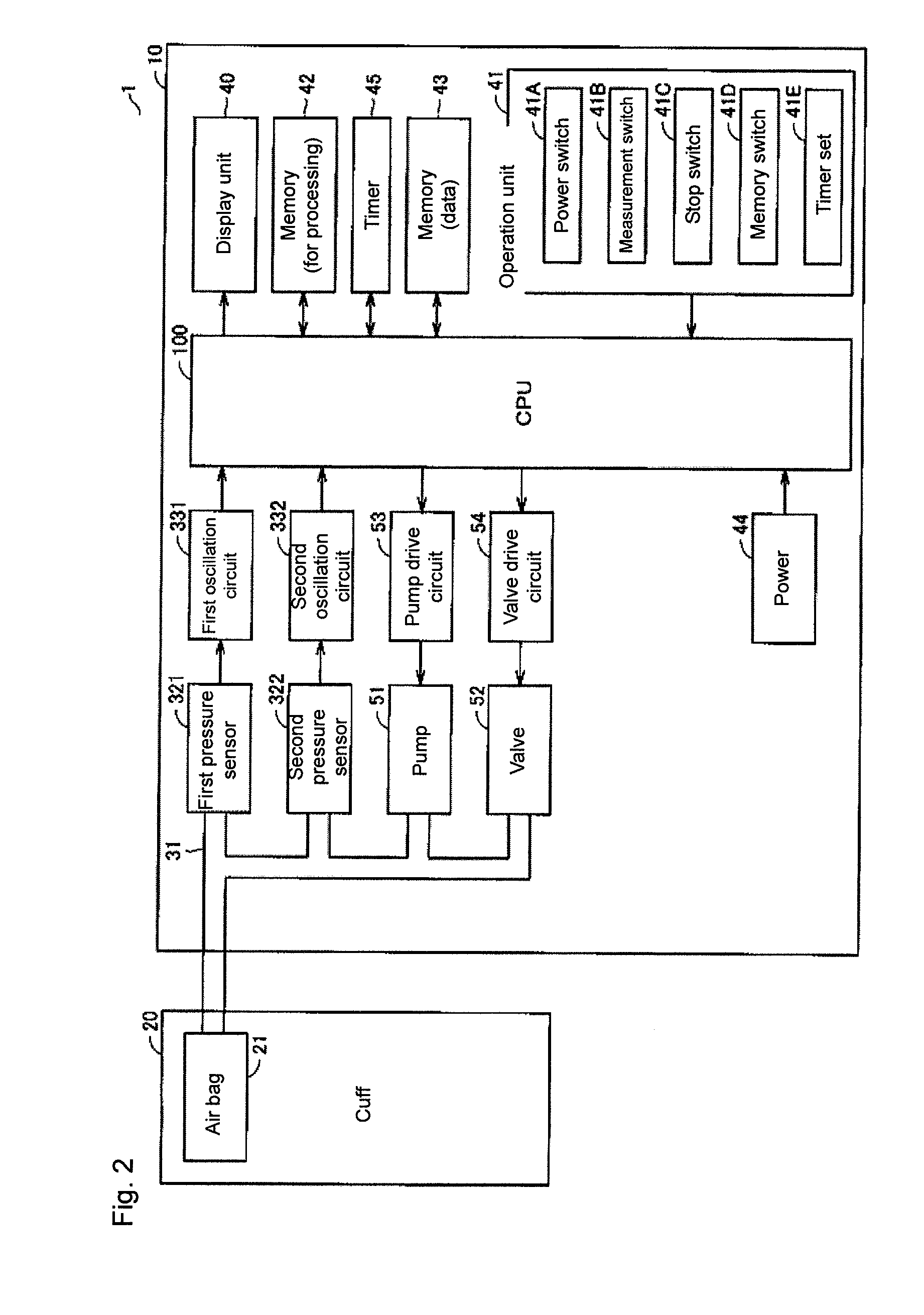
[0062]With reference to FIG. 1 and FIG. 2, an electronic sphygmomanometer 1 includes a main body 10, and a cuff 20 that can be wrapped around an upper arm of a person to be measured. The cuff 20 includes an air bag 21. A display unit 40 configured by liquid crystals or the like, and an operation unit 41 including a plurality of switches for accepting instructions from a user (person to be measured) are arranged on a surface of the main body 10.

[0063]The main body 10 includes the display unit 40 and the operation unit 41 described above. The main body 10 includes a CPU (Central Processing Unit) 100 ...

second embodiment

[0118]According to a second embodiment of the present invention, an electronic sphygmomanometer 1A has an outer appearance different from the electronic sphygmomanometer 1 of FIG. 1 applied in the first embodiment. The function configuration of FIG. 2 is realized also in the electronic sphygmomanometer 1A. Furthermore, the procedure of abnormality detection of the pressure sensor and the procedure of the blood pressure measurement described in the first embodiment can also be applied to the electronic sphygmomanometer 1A.

[0119]FIG. 9 and FIG. 10 each show the outer appearance of the electronic sphygmomanometer 1A. The schematic appearance of the electronic sphygmomanometer 1A in a state where a cuff is detached from a main body is shown in FIG. 9, and the schematic appearance of the electronic sphygmomanometer 1A in a state where the cuff is attached to the main body is shown in FIG. 10.

[0120]As shown in FIG. 9 and FIG. 10, the electronic sphygmomanometer 1A mainly includes a main b...

third embodiment

[0138]The configuration for detecting the abnormality of the pressure sensor is not limited to those described in the first and second embodiments, but may be detected by the configuration according to a third embodiment.

[0139]FIG. 14 and FIG. 15 show a hardware configuration and a function configuration of an electronic sphygmomanometer 1C according to the third embodiment.

[0140]Comparing the configuration of FIG. 14 and the configuration of FIG. 2 according to the first embodiment, the difference therebetween is that the electronic sphygmomanometer 1C in FIG. 14 includes a main body 101 in place of the main body 10 in FIG. 2.

[0141]In addition to the configuration of FIG. 2, the main body 101 includes therein a tank 57 for storing a constant volume of air, a switching valve 56 connected to the tank 57 through the air tube 31, and a switching valve drive circuit 55 for controlling the opening and closing operations of the switching valve 56. The main body 101 in FIG. 14 includes a C...


PUM


Abstract

An electronic sphygmomanometer has a cuff to be attached to a measurement site, a pressurization / depressurization unit for adjusting a pressure to be applied to the cuff, a pressure detection unit including a plurality of pressure sensors, for detecting cuff pressures in the cuff based on pressure information output from the plurality of pressure sensors, and a blood pressure calculating unit for calculating a blood pressure based on a change in the cuff pressures detected by the pressure detection unit. Blood pressure measurement and detection of abnormality on the plurality of pressure sensors are carried out based on the cuff pressures respectively corresponding to the plurality of pressure sensors detected according to the pieces of pressure information output from the plurality of pressure sensors.

Description

BACKGROUND OF THE INVENTION[0001]1. Technical Field[0002]The present invention relates to electronic sphygmomanometers, and in particular, to an electronic sphygmomanometer for enhancing the reliability of a blood pressure measurement value.[0003]2. Background Art[0004]The blood pressure is one of indices for analyzing the cardiovascular diseases. Performing the risk analysis of the cardiovascular disease based on the blood pressure is effective in preventing cardiovascular diseases such as apoplexy, cardiac arrest, and cardiac infarct. The early morning high blood pressure in which the blood pressure rises early in the morning is related to heart diseases, apoplexy, and the like. Furthermore, a symptom in which the blood pressure suddenly rises between one hour and one and a half hour after waking up, called as the morning surge, in the early morning high blood pressure is known to have a causal connection with apoplexy. Therefore, it is useful in the risk analysis of the cardiovas...

Claims


Application Information

Patent Timeline
IPC IPC(8): A61B5/0225
CPCA61B5/02225A61B5/0225A61B5/7221A61B5/02233
Inventor SAWANOI, YUKIYAKISHIMOTO, HIROSHITOMIOKA, MASAKIMATSUMURA, NAOMIFUJITA, REIJITAMAKI, YUUICHIROYAMASHITA, SHINGO
Owner OMRON HEALTHCARE CO LTD
Why Eureka
Try Eureka