Eureka AIR delivers breakthrough ideas for toughest innovation challenges, trusted by R&D personnel around the world.

Crop sample presentation system

a sample and presentation system technology, applied in the field of sample presentation system, can solve the problems of inability to reliably detect grain properties, unsuitable arrangement,

Active Publication Date: 2011-06-23
DEERE & CO
View PDF12 Cites 6 Cited by
  • Summary
  • Abstract
  • Description
  • Claims
  • Application Information

AI Technical Summary

Benefits of technology

The patent describes a system for collecting a sample of crop from a harvesting machine and measuring its properties using a sensor. The system includes a bypass line that is angled upward, allowing the crop to be fed through without damage. This prevents segregation effects and ensures a representative sample of the crop is collected. The technical effect of this system is to provide accurate and reliable data on the quality of the crop during harvesting.

Problems solved by technology

This arrangement is not suited for checking properties of grain, since it would destroy the kernels.
When grain is fed in a horizontal auger, like in the prior art cross augers, and the sensor looks into the interior of the auger tube, the problem arises that when the crop flow is relatively low, such that crop is only present at the bottom of the tube, no reliable sensing is possible due to lack of sufficient crop material in front of the sensor.
A similar problem arises when the harvesting machine drives up or down a hill.
Mounting the sensor at the bottom of the auger tube, such that it looks upward upon the crop, does not resolve this problem, since smaller particles of the crop collect at the bottom of the tube, while the grain collects above these smaller particles.

Method used


Image

  • Crop sample presentation system
  • Crop sample presentation system
  • Crop sample presentation system

Examples


Embodiment Construction

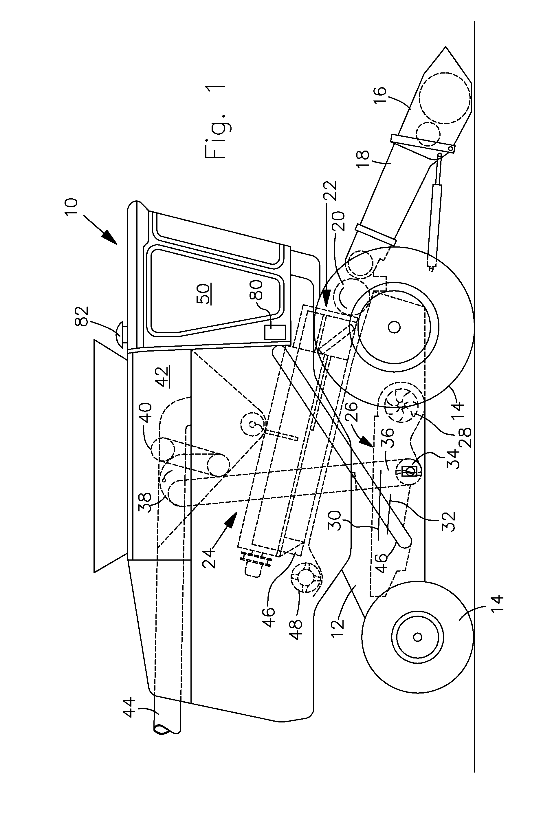
[0014]Referring now to FIG. 1, therein is shown an agricultural vehicle in the form of a harvester or combine 10 comprising a main frame 12 having driven front and steerable rear ground engaging wheels 14 supporting the main frame for forward movement over a field of crop to be harvested. Although wheels 14 are shown, the combine 10 could be supported entirely or in part on ground engaging tracks. Drive to the front wheels 14 is provided through a conventional hydrostatic transmission by an internal combustion engine mounted on the frame 12. In the following, references to directions (like forward) are cited with respect to the forward direction of combine 10 that is directed to the right in FIG. 1.

[0015]A vertically adjustable header in the form of a harvesting platform 16 is used for harvesting a crop and directing it to a feederhouse 18. The feederhouse 18 is pivotally connected to the frame 12 and includes a conveyor for conveying the harvested crop to a beater 20. The beater 20...


PUM


Abstract

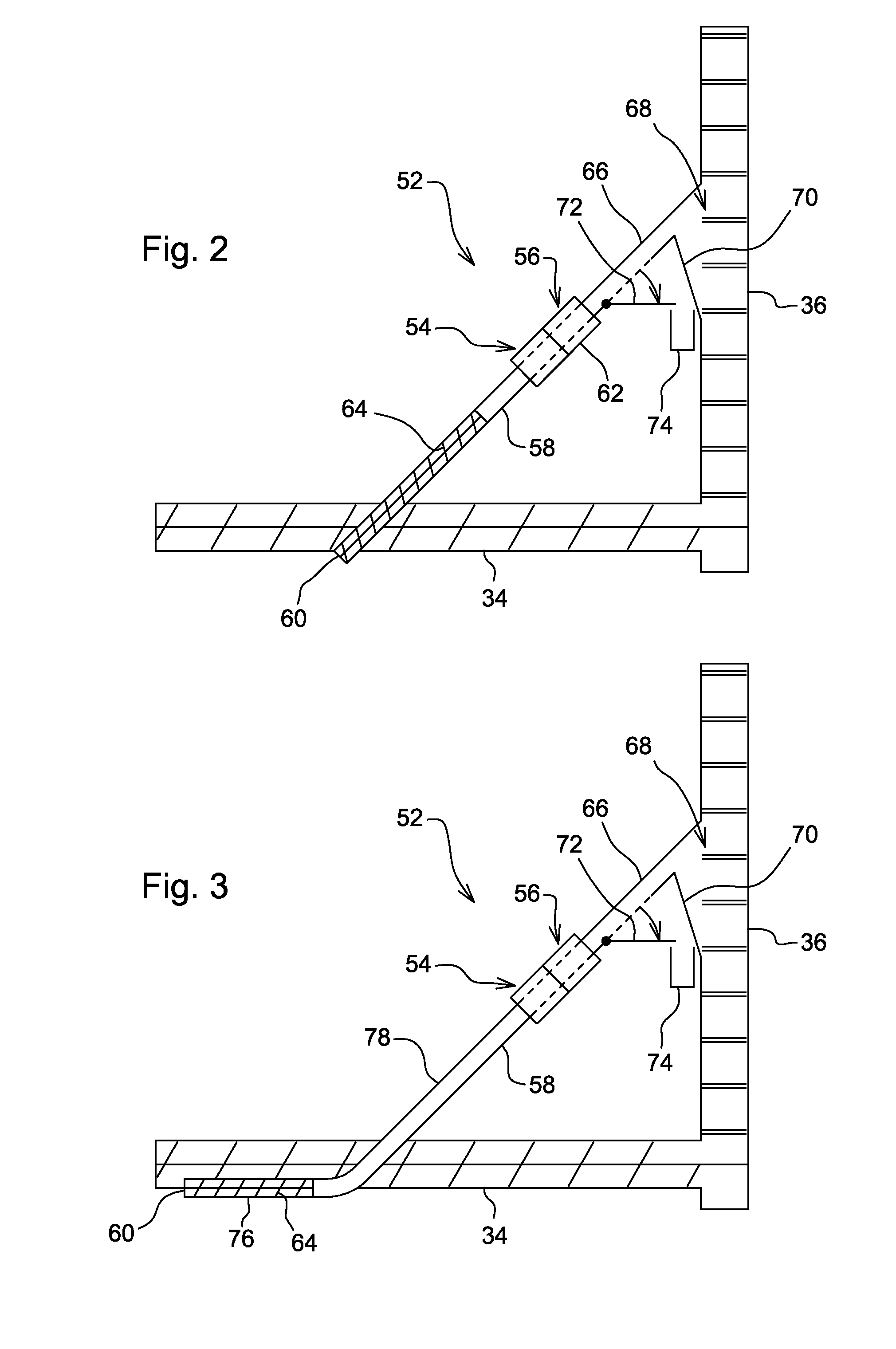
A system for presenting a crop sample to a crop property sensor is in particular suited for a harvesting machine and comprises a bypass line branching off from a crop feeding assembly, a conveyor for feeding the branched-off crop through the bypass line without damaging the crop, and a crop property sensor for sensing one or more properties of the crop in the bypass line. The bypass line is upwardly angled or extends vertical, such that the conveyor elevates the material from the crop guiding channel to the crop property sensor.

Description

CROSS REFERENCE TO RELATED-APPLICATION[0001]This document (including the drawings) claims priority based on U.S. provisional application No. 61 / 285,578, filed on Dec. 11, 2009 and entitled Crop Sample Presentation System, under 35 U.S.C. 119(e).FIELD OF THE INVENTION[0002]The present invention relates to a sample presentation system for presenting a crop sample to a sensor in a harvesting machine.BACKGROUND OF THE INVENTION[0003]Combines are large machines that harvest, thresh and clean grain in a field. A combine comprises a number of adjustable elements, like the size of openings in a threshing concave or in a separating grate, the speed of a cleaning shoe blower and the position of louvers in a sieve. The optimal working parameter of these elements depends on the crop type and properties and can change over time. The adjustment of these parameters is usually performed by the combine operator based upon instruction manuals or his experience or automatically based on values stored ...

Claims


Application Information

Patent Timeline
Patent Type & Authority Applications(United States)
IPC IPC(8): A01F12/46
CPCA01D41/127A01D41/1277
Inventor KORMANN, GEORGPHELAN, JAMES J.KOZICKI, ANDRZEJHERLITZIUS, THOMASTEICHMANN, JENSGUNTHER, ANDI
Owner DEERE & CO
Why Eureka
Eureka Blog
Learn More