
Optical diagnosis using measurement sequence

a technology of aberration and optical diagnosis, applied in the field of optical diagnosis using aberration measurements, can solve problems such as different aberrations, changes in eye aberrations, and complicated determination of customized refractive corrections

Active Publication Date: 2011-06-23
AMO DEVMENT
View PDF44 Cites 52 Cited by
  • Summary
  • Abstract
  • Description
  • Claims
  • Application Information

AI Technical Summary

Benefits of technology

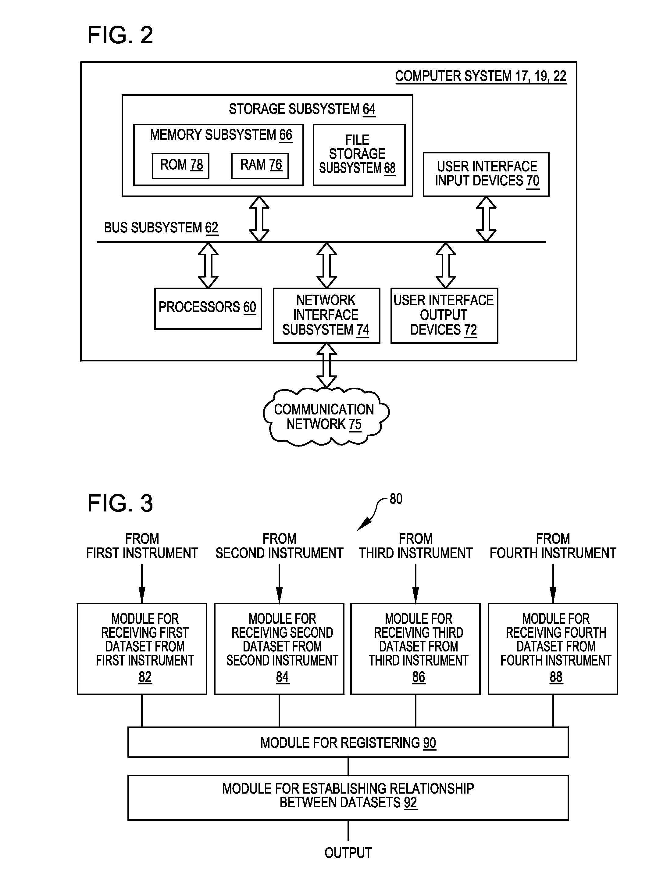
In many embodiments, statistically-significant component aberrations of the eye are determined by analyzing a sequence of aberrations measurements. Each aberration measurement of the sequence can be used to determine component aberrations that, when combined, approximate the combined aberrations of the eye for that measurement. Each of the resulting series of component aberrations can be analyzed to quantify how any particular component aberration changes over time. In many embodiments, the eye is subjected to different viewing conditions during the sequence of aberration measurements so that the effect of the different viewing conditions on the component aberrations can be determined. The determination of how the component aberrations change over time, and change with respect to different viewing conditions, provides data that can be used to select an optical correction for the eye. In many embodiments, one or more candidate optical corrections are evaluated relative to different viewing conditions so as to aid in the selection of an optical correction for the eye.

Problems solved by technology

The determination of a customized refractive correction for an eye may be complicated by the often dynamic nature of the refraction of an eye.
Even for viewing distances within an accommodation range of an eye, different accommodation levels have different levels of muscular contraction, which may result in different aberrations due to, for example, changes in the shape of the eye arising from different internal strain levels in the eye.
Even changes in the moisture level of the eye (e.g., tear film) can produce changes in the aberrations of the eye.

Method used


Image

  • Optical diagnosis using measurement sequence
  • Optical diagnosis using measurement sequence
  • Optical diagnosis using measurement sequence

Examples


Embodiment Construction

In the following description, various embodiments of the present invention will be described. For purposes of explanation, specific configurations and details are set forth in order to provide a thorough understanding of the embodiments. However, it will also be apparent to one skilled in the art that the present invention may be practiced without the specific details. Furthermore, well-known features may be omitted or simplified in order to not obscure the embodiment being described.

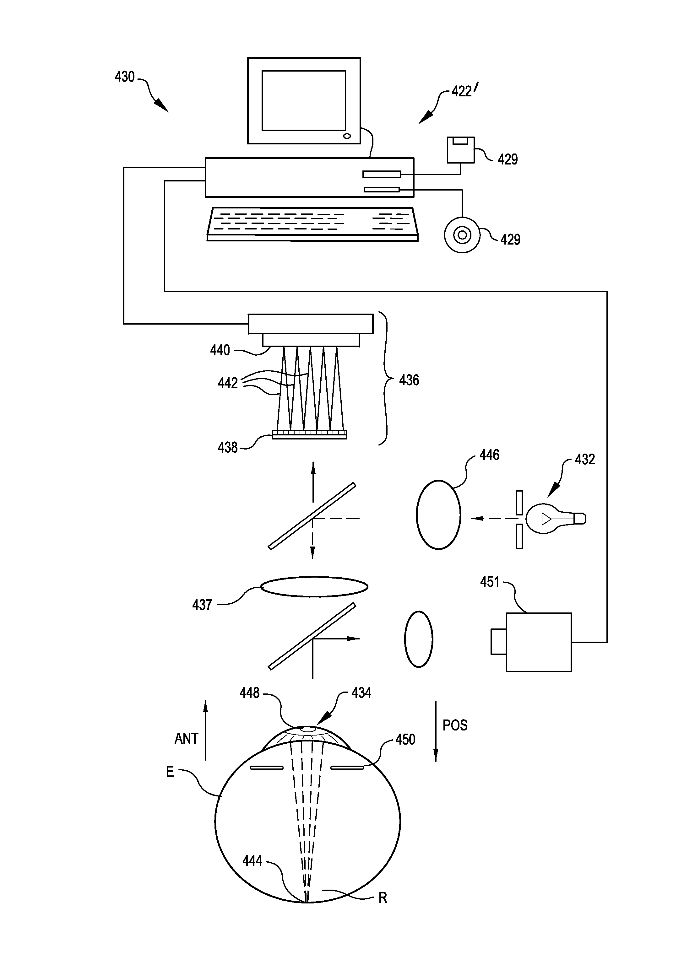
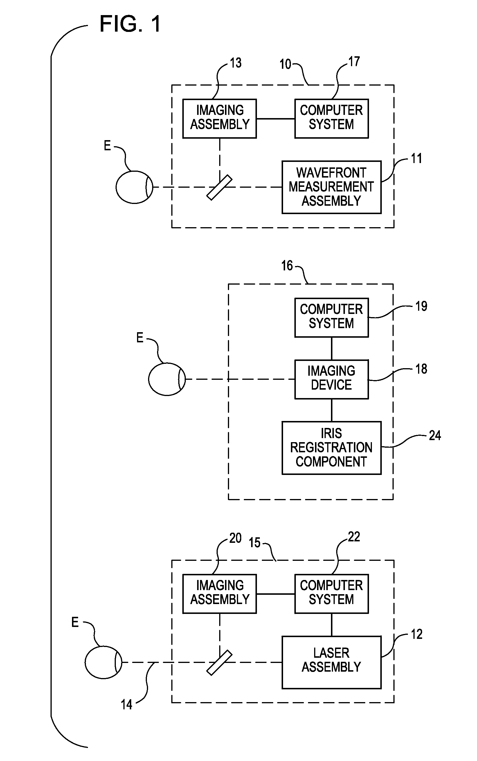
Embodiments herein provide devices, systems, and methods that facilitate optical analysis, particularly for the diagnosis and treatment of refractive errors of the eye. Embodiments of the invention facilitate the use of multi-modal diagnostic instruments and instrument systems, making it easier to acquire and fuse (e.g., synthesize) data from different measurements of the eye. For example, wavefront aberrometry may be fused with corneal topography, optical coherence topography and wavefront, optical coh...


PUM


Abstract

Devices, systems, and methods that facilitate optical analysis, particularly for the diagnosis and treatment of refractive errors of the eye. An optical diagnostic method for an eye includes obtaining a sequence of aberration measurements of the eye, identifying an outlier aberration measurement of the sequence of aberration measurements, and excluding the outlier aberration measurement from the sequence of aberration measurements to produce a qualified sequence of aberration measurements. The sequence of aberrations measurements can be obtained by using a wavefront sensor. An optical correction for the eye can be formulated in response to the qualified sequence of aberration measurements.

Description

BACKGROUNDThe present application relates generally to optical diagnosis using aberration measurements, and relates more particularly to the use of one or more sequences of aberration measurements to produce an optical diagnosis. In many embodiments, a sequence of aberrations measurements are obtained and used to quantify the aberrations of an eye. The quantified aberrations are then used to produce an optical diagnosis for the eye.Known laser eye procedures generally employ an ultraviolet or infrared laser to remove a microscopic layer of stromal tissue from the cornea of the eye to alter the refractive characteristics of the eye. The laser removes a selected shape of the corneal tissue, often to correct refractive errors of the eye. Ultraviolet laser ablation results in photo-decomposition of the corneal tissue, but generally does not cause significant thermal damage to adjacent and underlying tissues of the eye. The irradiated molecules are broken into smaller volatile fragments ...

Claims


Application Information

Patent Timeline
IPC IPC(8): A61B3/103A61B3/10A61B3/11
CPCA61B3/0025G02C7/027G02C7/04A61B3/1015A61B3/103A61B3/112
Inventor NEAL, DANIEL R.RAYMOND, THOMAS D.ZICKLER, LEANDER
Owner AMO DEVMENT
Learn More