
Multi-input multi-output antenna for improving isolation

a multi-output, antenna technology, applied in the direction of antennas, antenna details, antenna couplings, etc., can solve the problems of difficult to improve the isolation characteristic and interference between the antennas, and achieve the effect of preventing current from flowing and improving the isolation characteristic of the antenna

Inactive Publication Date: 2011-06-23
ELECTRONICS & TELECOMM RES INST
View PDF5 Cites 26 Cited by
  • Summary
  • Abstract
  • Description
  • Claims
  • Application Information

AI Technical Summary

Benefits of technology

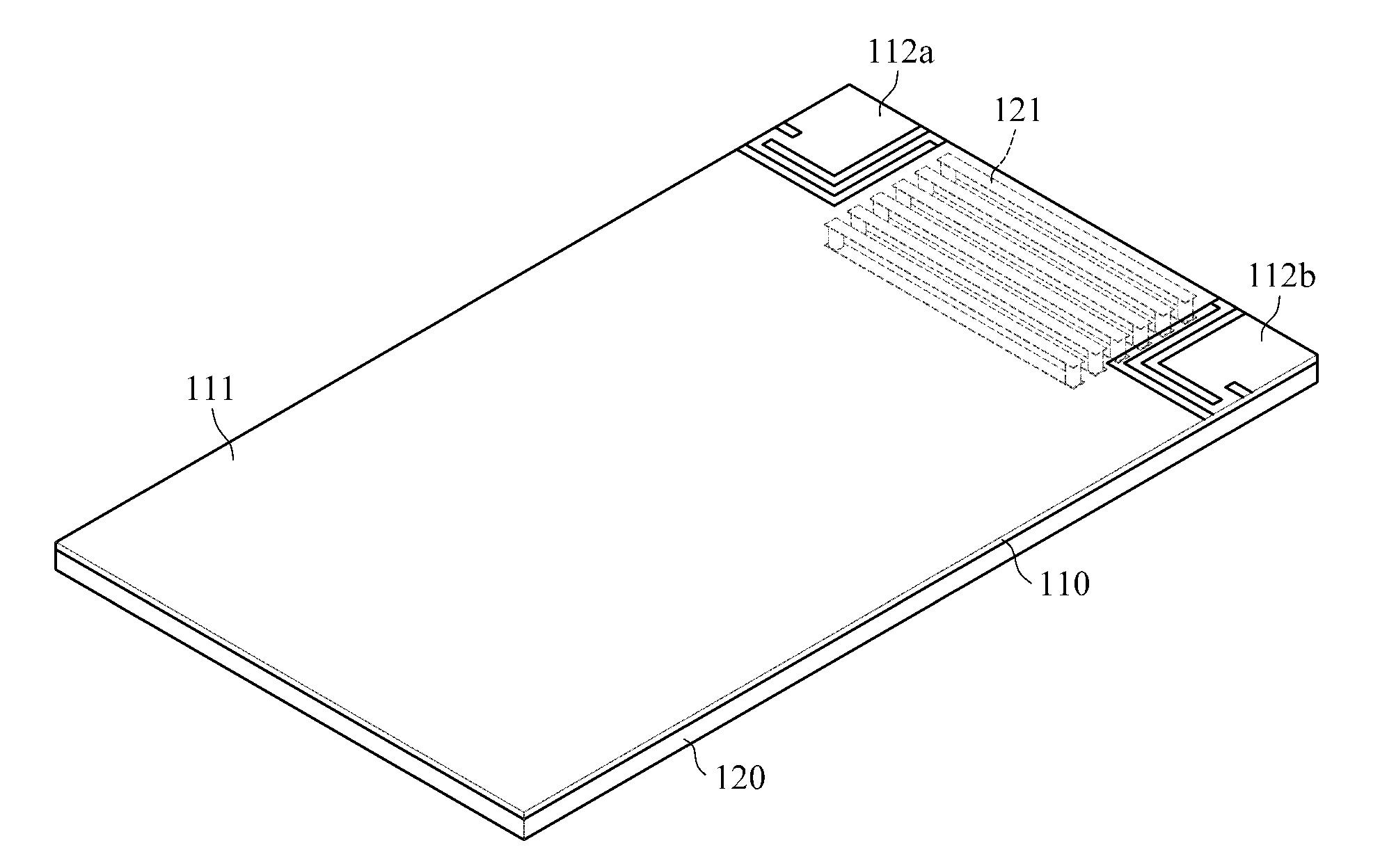
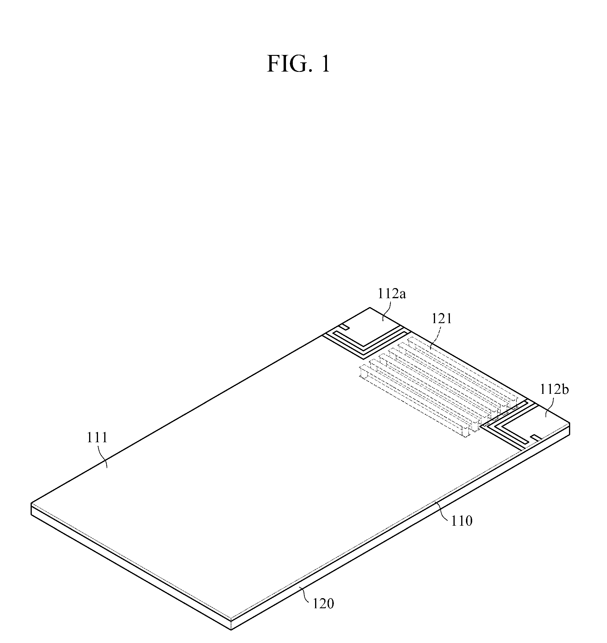
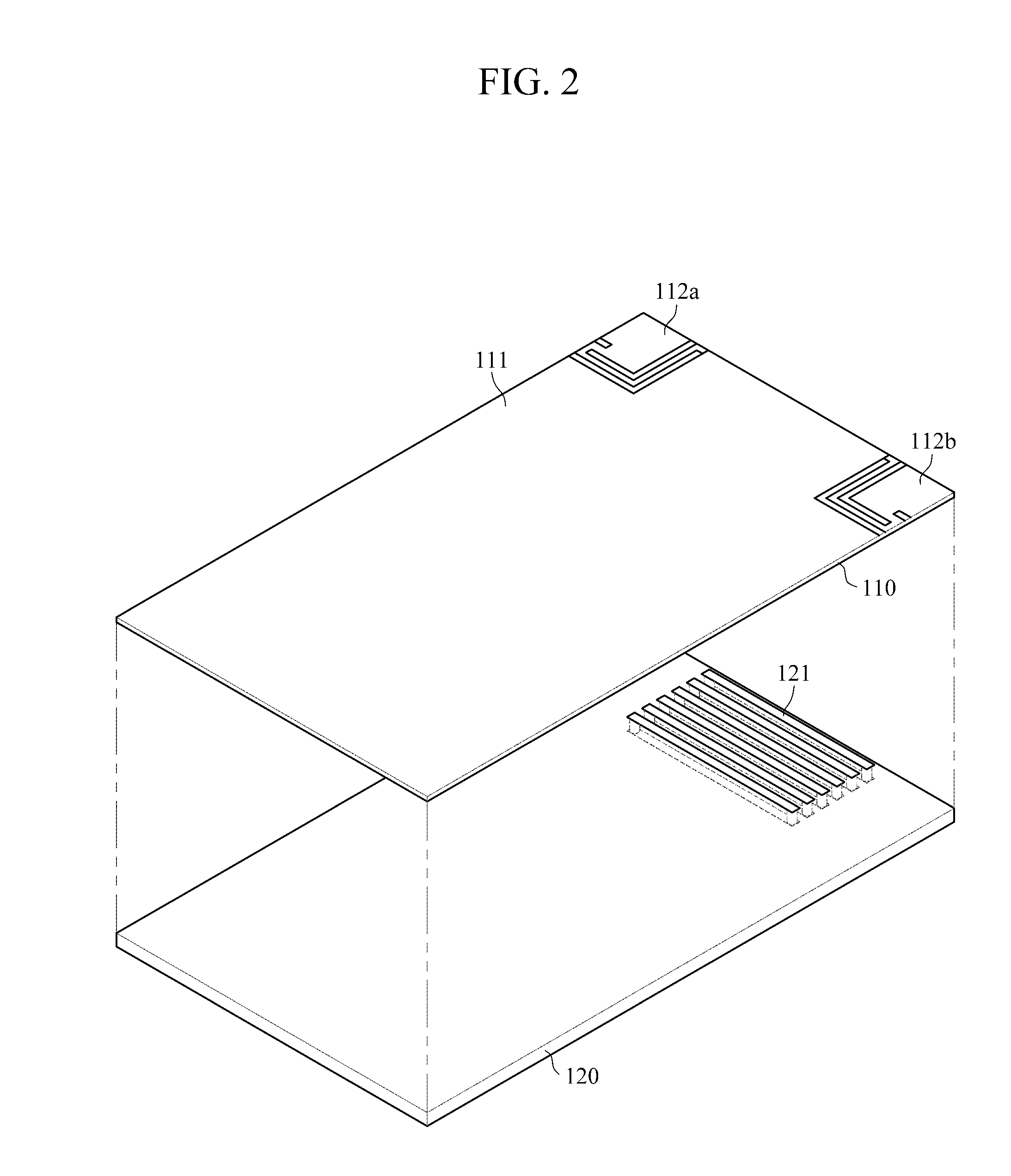
[0008]The following description relates to a multi-input multi-output (MIMO) antenna which causes permeability of split ring resonators (SRRs) to have a negative value using a structural arrangement of the SRRs and thus can prevent current from flowing between antennas and improve the isolation characteristic of the antennas.
[0009]In an exemplary embodiment of the present invention, SRRs are structurally arranged on the lower end of a ground surface between a plurality of antenna patterns of an MIMO antenna spaced apart from each other. Thus, permeability of the SRRs has a negative value, which prevents current from flowing between antennas. Consequently, the exemplary embodiment of the present invention can improve the isolation characteristic of the antennas.

Problems solved by technology

Since a plurality of antennas are used in a MIMO antenna system, interference may occur between the antennas.
Meanwhile, to implement a MIMO antenna system in a wireless portable terminal, two or more antenna elements should be disposed in a space smaller than half a wavelength, and thus it is difficult to improve the isolation characteristic.

Method used


Image

  • Multi-input multi-output antenna for improving isolation
  • Multi-input multi-output antenna for improving isolation
  • Multi-input multi-output antenna for improving isolation

Examples


Embodiment Construction

[0019]The invention is described more fully hereinafter with reference to the accompanying drawings, in which exemplary embodiments of the invention are shown. This invention may, however, be embodied in many different forms and should not be construed as limited to the exemplary embodiments set forth herein. Rather, these exemplary embodiments are provided so that this disclosure is thorough, and will fully convey the scope of the invention to those skilled in the art. In the drawings, the size and relative sizes of layers and regions may be exaggerated for clarity. Like reference numerals in the drawings denote like elements.

[0020]FIG. 1 is a perspective view of a multi-input multi-output (MIMO) antenna for improving isolation according to an exemplary embodiment of the present invention. FIG. 2 is an assembly perspective view of the MIMO antenna for improving isolation shown in FIG. 1. As shown in FIGS. 1 and 2, a MIMO antenna for improving isolation according to this exemplary e...


PUM


Abstract

A multi-input multi-output (MIMO) antenna for improving isolation is provided. Split ring resonators (SRRs) are structurally arranged on the lower end of a ground surface between a plurality of antenna patterns spaced apart from each other. Accordingly, permeability of the SRRs has a negative value, which prevents current from flowing between antennas. Consequently, the isolation characteristic of the antennas is improved.

Description

CROSS REFERENCE TO RELATED APPLICATION[0001]This application claims the benefit under 35 U.S.C. §119(a) of Korean Patent Application No. 10-2009-0127249, filed on Dec. 18, 2009, in the Korean Intellectual Property Office, the entire disclosure of which is incorporated herein by reference for all purposes.BACKGROUND[0002]1. Field[0003]The following description relates to a multi-input multi-output (MIMO) antenna for improving isolation, and more particularly, to technology for preventing mutual interference between a plurality of antennas in a MIMO antenna system in which the antennas are arranged.[0004]2. Description of the Related Art[0005]Since a plurality of antennas are used in a MIMO antenna system, interference may occur between the antennas. Thus, a radiation pattern may be distorted, or mutual coupling between antenna elements may occur.[0006]Meanwhile, to implement a MIMO antenna system in a wireless portable terminal, two or more antenna elements should be disposed in a sp...

Claims


Application Information

Patent Timeline
IPC IPC(8): H01Q1/52H01Q21/00H01Q5/10
CPCH01Q1/38H01Q1/521H01Q21/28H01Q13/08H01Q5/10
Inventor CHOI, JAE-HOONCHOI, JAE-ICKKIM, DONG-HOJUNG, HAE-IIKIM, JUNG-PYOLEE, YOUNG-KI
Owner ELECTRONICS & TELECOMM RES INST
Learn More