
Apparatus and Methods for Pneumatically-Assisted Electrospray Emitter Array

a technology of electrospray and emitter array, which is applied in the field of mass spectrometry and mass spectrometer, can solve the problems of nanospray being limited in its application to low flow analysis, the mass spectrometer system is more sensitive, and the flow rate is much larger, so as to achieve the effect of small initial droplets and easy de-solvation

Active Publication Date: 2011-06-23
THERMO FINNIGAN
View PDF33 Cites 32 Cited by
  • Summary
  • Abstract
  • Description
  • Claims
  • Application Information

AI Technical Summary

Benefits of technology

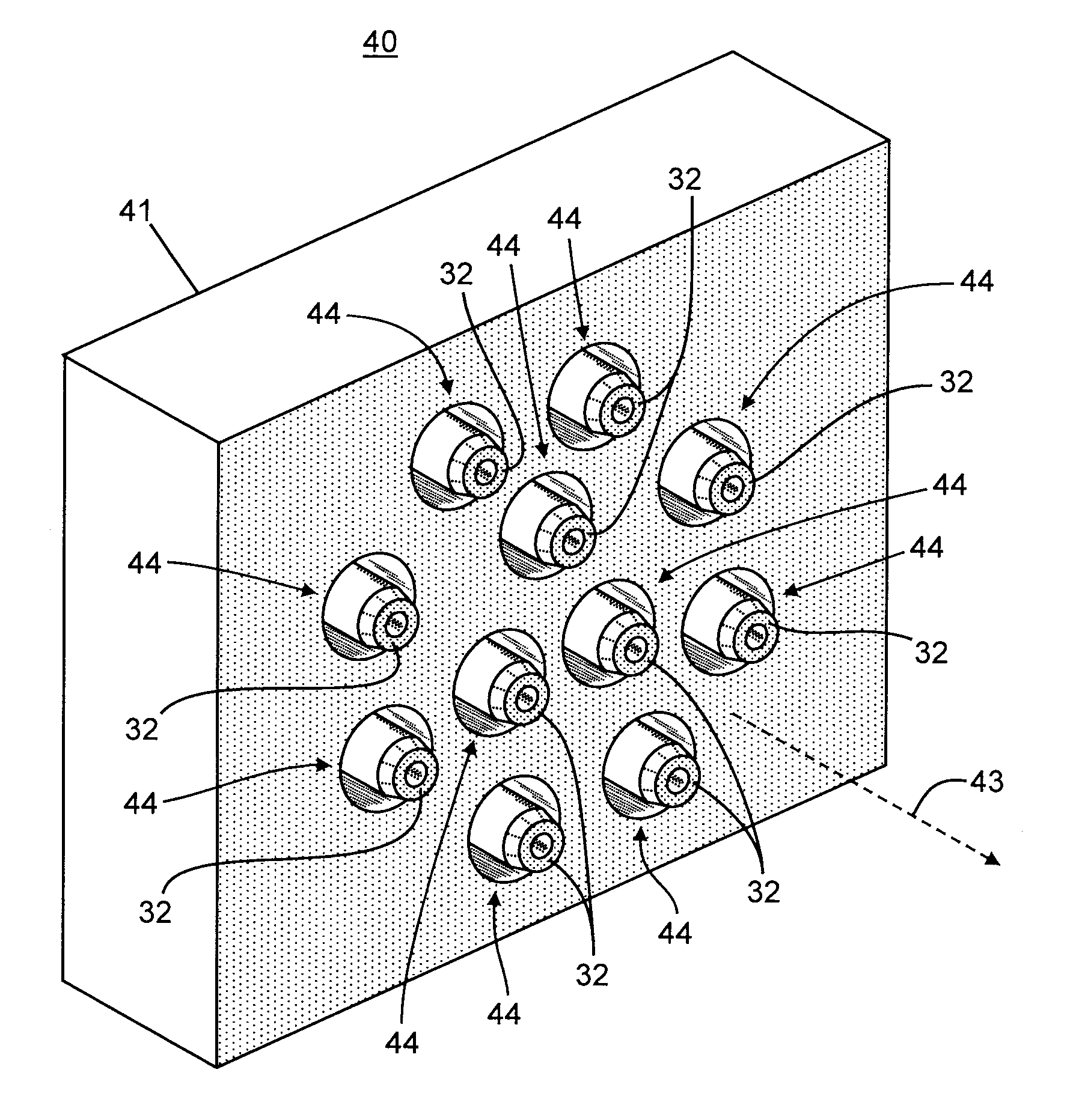
[0022]We herein disclose novel electrospray ion sources and methods that take all of the above issues into consideration. The conventional single electrospray emitter within a single concentric sheath gas flow tube is replaced with a plurality of electrospray assemblies, each of which carries a fraction of the total flow of analyte-bearing liquid and that receives pneumatic assistance from circumferentially surrounding sheath gas flow. As non limiting examples, the number of these electrospray emitters can be as low as 2 or 3, and can easily be envisioned to be 15 or even higher.
[0023]In a first aspect of the invention, there is disclosed an electrospray ion source for a mass spectrometer comprising: a source of an analyte-bearing liquid; a source of a sheath gas; a plurality of liquid conduits, each liquid conduit configured so as to receive a portion of the analyte-bearing liquid from the source of analyte-bearing liquid; at least one electrode for producing electrospray emission of charged droplets from an outlet of each of said liquid conduits under application of an electrical potential to the at least one electrode; a power supply electrically coupled to the at least one electrode for maintaining the at least one electrode at the electrical potential; and a plurality of sheath gas conduits, each sheath gas conduit comprising: an inlet configured to receive a sheath gas portion from the source of sheath gas; and an outlet configured to emit a sheath gas flow that circumferentially surrounds, in at least two dimensions, a portion of the charged droplets emitted from a respective one of the liquid conduit outlets.
[0024]In a second aspect of the invention, there is disclosed an electrospray ion source for a mass spectrometer comprising: a source of an analyte-bearing liquid; a source of a sheath gas; a plurality of liquid conduits, each liquid conduit configured so as to receive a portion of the analyte-bearing liquid from the source of analyte-bearing liquid; at least one electrode for producing electrospray emission of charged droplets from an outlet of each of said liquid conduits under application of an electrical potential to the at least one electrode; a power supply electrically coupled to the at least one electrode for maintaining the at least one electrode at the electrical potential; and a sheath gas conduit comprising: an inlet configured to receive the sheath gas from the source of sheath gas; and an outlet configured to emit a sheath gas flow that circumferentially surrounds, in at least two dimensions, a portion of the charged droplets emitted from every one of the plurality of liquid conduit outlets.
[0025]In another aspect the invention, a method for providing ions to a mass spectrometer is disclosed, the method comprising: providing a source of an analyte-bearing liquid; providing a source of a sheath gas; providing a plurality of liquid conduits, each liquid conduit configured so as to receive a portion of the analyte-bearing liquid from the source of analyte-bearing liquid; providing at least one electrode associated with the plurality of liquid conduits; providing a plurality of sheath gas conduits, each sheath gas conduit comprising a sheath gas outlet configured to emit a sheath gas flow that circumferentially surrounds, in at least two dimensions, an outlet of a respective one of the liquid conduits; distributing the analyte-bearing liquid among the plurality of liquid conduits; distributing the sheath gas among the plurality of sheath gas conduits; and maintaining the at least one electrode at an electrical potential such that charged liquid droplets are emitted from the plurality of liquid conduits.
[0026]In yet another aspect of the invention, a method for providing ions to a mass spectrometer is disclosed, the method comprising: providing a source of an analyte-bearing liquid; providing a source of a sheath gas; providing a plurality of liquid conduits, each liquid conduit configured so as to receive a portion of the analyte-bearing liquid from the source of analyte-bearing liquid and having a respective outlet; providing at least one electrode associated with the plurality of liquid conduits; providing a sheath gas conduit comprising a sheath gas outlet configured to emit a sheath gas flow that circumferentially surrounds, in at least two dimensions, the outlets of the plurality of liquid conduit outlets; distributing the analyte-bearing liquid among the plurality of liquid conduits; providing the sheath gas to the sheath gas conduit; and maintaining the at least one electrode at an electrical potential such that charged liquid droplets are emitted from the plurality of liquid conduits.
[0027]In accordance with the present teachings, the diameters of each of a plurality of electrospray emitting capillaries may be smaller than is the case for a conventional single capillary. Such smaller capillaries can generate smaller initial droplets which are more readily de-solvated. Further, the smaller capillary size enables all of the electrospray emitters to be in close proximity to one another so that ions are directed to an ion inlet of a mass spectrometer. Although the emitters are in close mutual proximity, nonetheless, they are each surrounded by nebulizing sheath such that their individual Taylor cones are not perturbed and also coalescence of liquid from different sprayers does not occur. In various embodiments, each liquid capillary or conduit may be configured so as to admit a flow rate of an analyte-bearing liquid portion of between 1 microliter per minute and 1 milliliter per minute through the capillary or conduit. The total flow rate, summed over all capillaries or conduits, may range from approximately 10 microliters per minute up to approximately 10 milliliters per minute.

Problems solved by technology

The smaller the initial size of the droplets, the more efficiently they can be desolvated, and eventually, the more sensitive the mass spectrometer system becomes.
Unfortunately, due to the small-diameter emitter needles employed in nanospray ionization, there is a maximum to the amount of liquid flow that can be accommodated.
Therefore, nanospray is limited in its applications to low flow analysis.
However, in LC-MS (Liquid Chromatography-Mass Spectrometry) assays, much larger flow rates are encountered, often exceeding 100 microliters per minute and occasionally as high as 5 milliliters per minute.
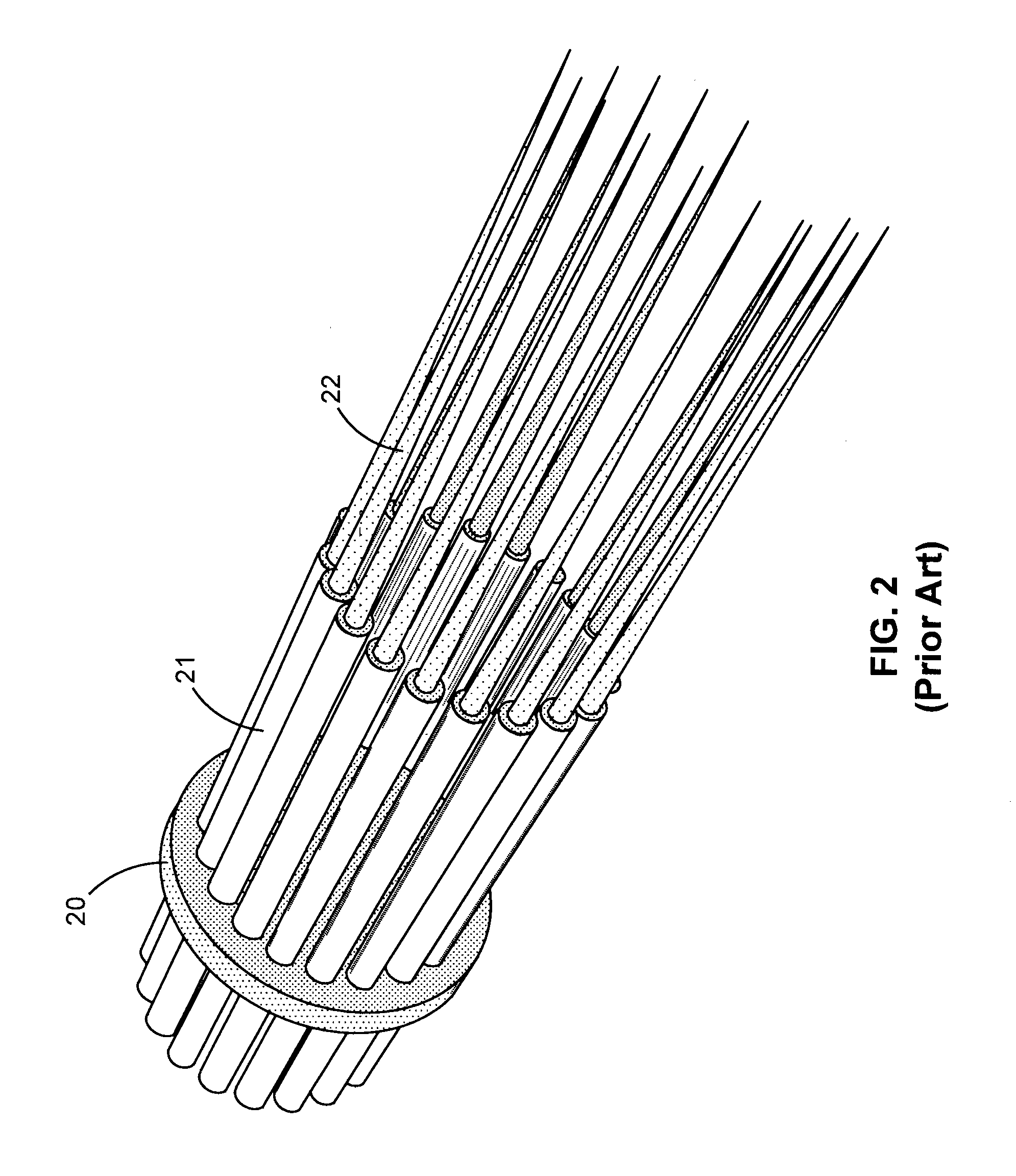
An issue with having a multitude of nanospray emitters is that the generated cloud of droplets starts to have dimensions that become incompatible with those of the inlet orifice of the mass spectrometer, in other words only a fraction of the mist generated is actually drawn into the inlet of the mass analyzer.
This loss obviously results in decreased sensitivity of the instrument.
This leads to additional costs, spatial requirements, shipping weight etc. all of which are not beneficial.
Yet, when there are multiple needles in close proximity, the spray from one needle could be negatively impacted by the electric field around a neighboring needle.
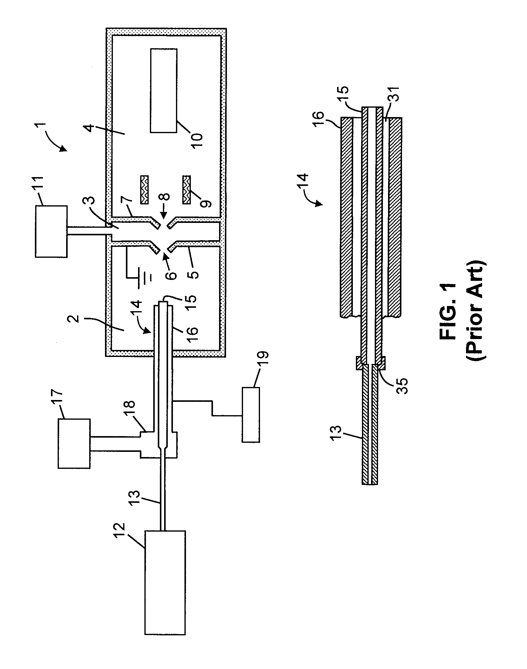
Although the apparatuses taught by Rossier et al. and by Li appear to operate adequately, they only provide for introduction of a sheath gas at a finite number of discrete gas channel ends adjacent to a fluid channel.
As a result, these apparatuses are subject to potential asymmetry or non-uniformity in the sheath pressure or flow rate around the emitted droplets or other charged particles.
If the gas is supplied from multiple channels, then restricted flow or clogging in one or more of the channels may cause similar difficulties.
Since sheath gas is supplied under pressure, the introduction of sheath gas in such an asymmetric or non-uniform fashion in such existing apparatuses, if not carefully controlled, may perturb the emission pattern and direction of electrospray droplets in a manner that causes fluctuations in the ability of ions to be captured by an ion inlet port of a mass spectrometer.
Further, since the outlets of both the sample and sheath liquid or gas microchannels, as described in the Rossier et al. apparatus, must fit within the dimensions of an individual Taylor cone, this apparatus is limited to nanospray flow regimes and is not suitable for providing variable flow rates in the range of hundreds of microliters to a few milliliters per minute, as would be expected when dividing a total sample flow of an LC-MS among a limited number of emitters.

Method used


Image

  • Apparatus and Methods for Pneumatically-Assisted Electrospray Emitter Array
  • Apparatus and Methods for Pneumatically-Assisted Electrospray Emitter Array
  • Apparatus and Methods for Pneumatically-Assisted Electrospray Emitter Array

Examples


Embodiment Construction

[0043]The present invention provides methods and apparatus for an improved ionization source for mass spectrometry. The following description is presented to enable one of ordinary skill in the art to make and use the invention and is provided in the context of a particular application and its requirements. It will be clear from this description that the invention is not limited to the illustrated examples but that the invention also includes a variety of modifications and embodiments thereto. Therefore the present description should be seen as illustrative and not limiting. While the invention is susceptible of various modifications and alternative constructions, it should be understood that there is no intention to limit the invention to the specific forms disclosed. On the contrary, the invention is to cover all modifications, alternative constructions, and equivalents falling within the essence and scope of the invention as defined in the claims. To more particularly describe th...


PUM

PropertyMeasurementUnit
outer diameteraaaaaaaaaa
thicknessaaaaaaaaaa

Abstract

An electrospray ion source comprises a source of analyte-bearing liquid; a source of sheath gas; a plurality of liquid conduits, each configured so as to receive a portion of the analyte-bearing liquid; at least one electrode associated with the plurality of liquid conduits for producing electrospray emission of charged droplets from an outlet of each of the liquid conduits; a power supply electrically coupled to the at least one electrode for maintaining the at least one electrodes at an electrical potential; and either one or a plurality of sheath gas conduits, each sheath gas conduit comprising an inlet configured to receive sheath gas and an outlet configured to emit a sheath gas flow that circumferentially surrounds, in at least two dimensions, a portion of the emitted charged droplets.

Description

FIELD OF THE INVENTION[0001]The present invention relates to mass spectrometry and mass spectrometers. More particularly, the invention relates to electrospray ion sources for and electrospray ion introduction into mass spectrometers.BACKGROUND OF THE INVENTION[0002]In electrospray ionization, a liquid is sprayed through the tip of a needle that is held at a high electric potential of a few kilovolts. Small multiply-charged droplets containing solvent molecules and analyte molecules are initially formed and then shrink as the solvent molecules evaporate. The shrinking droplets also undergo fission—possibly multiple times—when the shrinkage causes the charge density of the droplet to increase beyond a certain threshold. This process ends when all that is left of the droplet is a charged analyte ion that can be mass analyzed by a mass spectrometer. Some of the droplets and liberated ions are directed into the vacuum chamber of the mass spectrometer through an ion inlet orifice, such a...

Claims


Application Information

Patent Timeline
Patent Type & Authority Applications(United States)
IPC IPC(8): B01D59/44H01J49/26
CPCH01J49/167
Inventor WOUTERS, ELOY R.SPLENDORE, MAURIZIO A.DUNYACH, JEAN-JACQUES
Owner THERMO FINNIGAN
Learn More