
Multi-functional lamp

a multi-functional, lamp technology, applied in the field of lamps, can solve the problems of dangerous and even fatal riding the bike without, dangerous for joggers to jog or pedestrians to walk, and relative high risk of riding the bicycle in a dark pla

Inactive Publication Date: 2011-06-16
WEI HO SHENG
View PDF8 Cites 9 Cited by
  • Summary
  • Abstract
  • Description
  • Claims
  • Application Information

AI Technical Summary

Benefits of technology

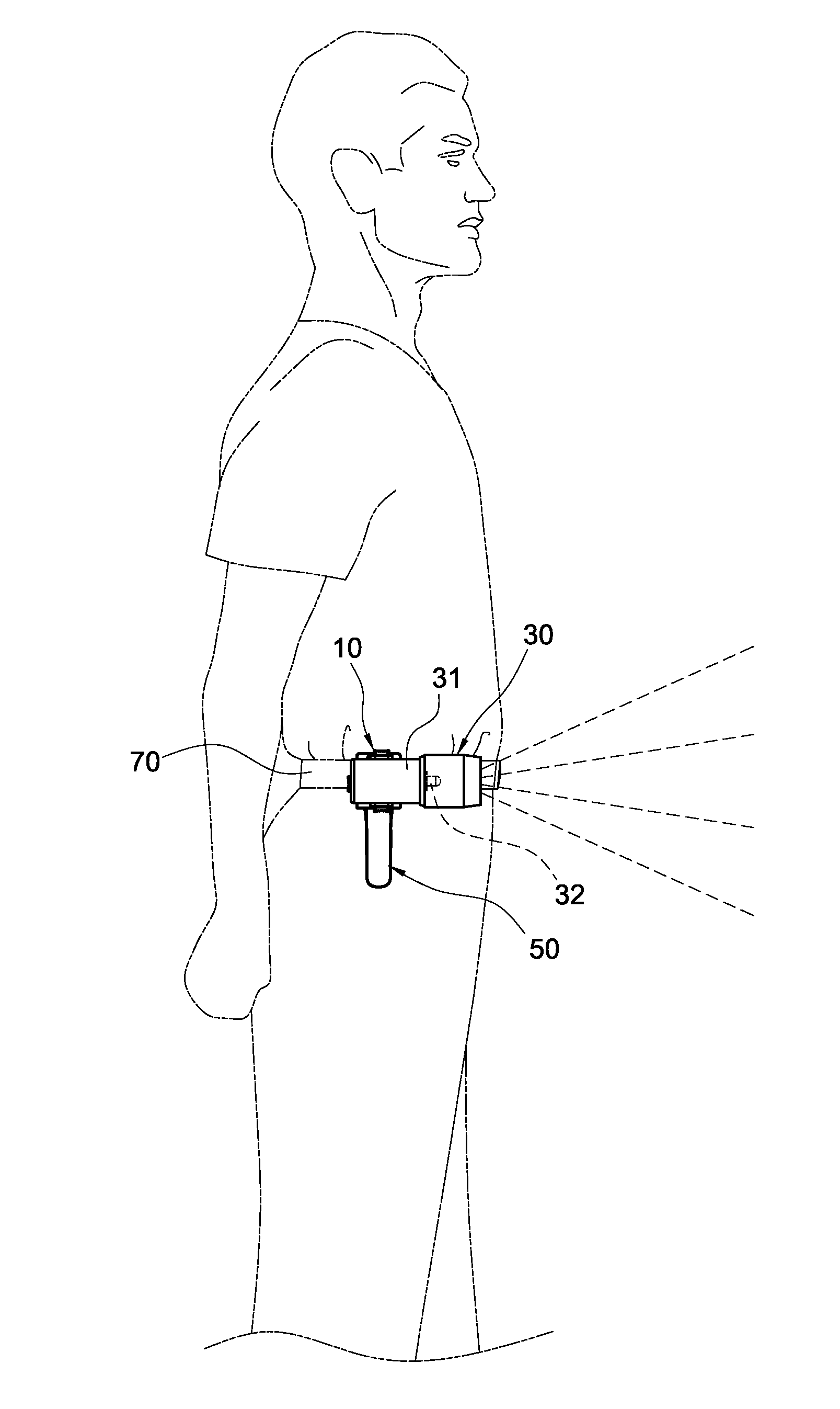
"The present invention provides a multi-functional lamp that can be installed on a bicycle or worn by a user for supplying illumination in a dark place. The lamp has an adjustable illumination angle to illuminate a target area. It can be used as a headlamp for bicyclists, a groundlamp for avoiding obstacles or pits, and a safety lamp for pedestrians to prevent accidents. The lamp is easy to install and use, providing a convenient and safe solution for night-time driving or activities."

Problems solved by technology

In general, a bicycle usually comes with a passive reflective plate installed at the rear of the bicycle to reflect the light of a coming motor vehicle behind the bicycle, and the bicycle usually has no active illumination lamp, and thus it is relatively a high risk to ride the bicycle in a dark place.
If a rider rides the bicycle on a rough road with obstacles and is not familiar with the road conditions, or even worse, there is a cliff in the front, it will be very dangerous and even fatal to ride the bike without having sufficient light and knowing the road conditions ahead.
In the morning or at nighttime, it is also dangerous for joggers to jog or pedestrians to walk on a road since drivers cannot see the joggers or pedestrians easily in the dark, and thus the pedestrians or joggers usually wear a reflective ring to reflect the light from the motor vehicle to warn the drivers.
However, the reflective plates or reflective rings are passive warning devices and cannot emit light, so that these devices can provide a low safety effect, and accidents may occur easily.

Method used


Image

  • Multi-functional lamp
  • Multi-functional lamp
  • Multi-functional lamp

Examples


Embodiment Construction

[0026]The technical characteristics, features and advantages of the present invention will become apparent in the following detailed description of the preferred embodiments with reference to the accompanying drawings. The drawings are provided for reference and illustration only, but not intended for limiting the present invention.

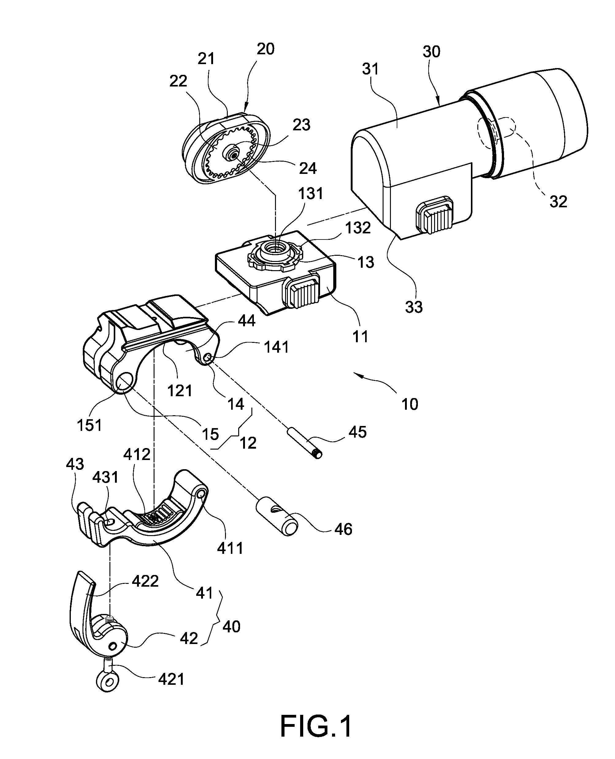
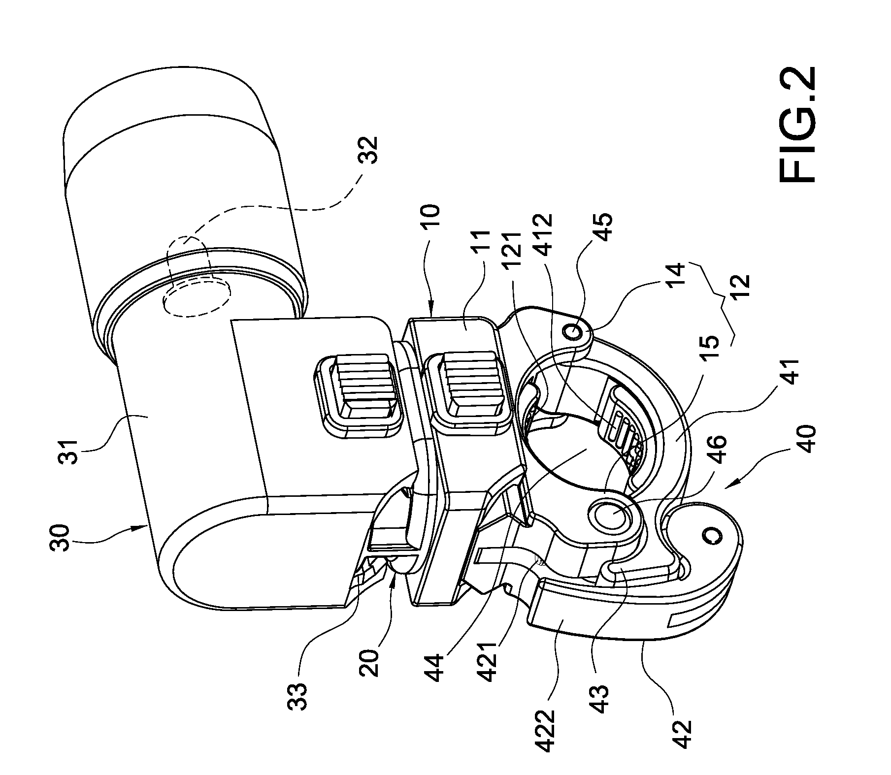
[0027]With reference to FIGS. 1 and 2 for a first preferred embodiment of a multi-functional lamp of the present invention, the multi-functional lamp comprises a carrier module 10, a rotating element 20, a light emitting module 30, and a compressing mechanism 40.

[0028]The carrier module 10 includes a base 11 and a curved arm 12 coupled to a side of the base 11, wherein a shaft 13 is formed and protruded from a surface of the base 11, and the shaft 13 has a shaft hole 131, and the shaft 13 includes an outer gear 132 protruded from the periphery of the shaft 13, and the curved arm 12 includes a front arm 14 and a rear arm 15, and the front arm 14 has a fron...


PUM


Abstract

A multi-functional lamp includes a carrier module, a rotating element, a light emitting module, a compressing mechanism and an elastic clamp mechanism. The carrier module includes a base and a curved arm coupled to the base. The base includes a shaft protruded thereon, and the rotating element is pivotally coupled to the shaft, and the light emitting module is coupled to the rotating element, and the compressing mechanism is pivotally coupled to the curved arm and enclosed with the curved arm to form a containing groove, and the elastic clamp mechanism includes an elastic element, such that the lamp can be installed on a bicycle or worn on a user's body to provide active illumination for a dark place with insufficient light and an illumination angle of the lamp can be adjusted to illuminate a target area.

Description

BACKGROUND OF THE INVENTION[0001]1. Field of the Invention[0002]The present invention relates to a lamp, and more particularly to a multi-functional lamp capable of adjusting its illumination angle.[0003]2. Description of Prior Art[0004]Since people pay more and more attention to leisure activities, particularly to mild fitness exercises such as bicycle riding and jogging, as well as the concept of environmental protection arising from energy crisis and increasingly higher oil price, and bicycles consume no petroleum and cause no noise or pollution, therefore bicycles not just serve as a fitness equipment, but also provide a transportation means for commuters. In general, a bicycle usually comes with a passive reflective plate installed at the rear of the bicycle to reflect the light of a coming motor vehicle behind the bicycle, and the bicycle usually has no active illumination lamp, and thus it is relatively a high risk to ride the bicycle in a dark place. If a rider rides the bic...

Claims


Application Information

Patent Timeline
Patent Type & Authority Applications(United States)
IPC IPC(8): B60Q1/06
CPCB62J6/02F21V21/145F21V21/0885B62J6/03
Inventor WEI, HO-SHENG
Owner WEI HO SHENG
Learn More