
Safety Ring Lid Closure

a safety ring and lid technology, applied in the direction of lids/covers, non-removal, transportation and packaging, etc., can solve the problems of most difficult to trim consistently, cut or abrasion to the skin, injury to the skin on other parts of the body coming into contact with a sharp rim or excess flash, etc., to overcome the risk of injury

Inactive Publication Date: 2011-06-09
MEDICAL ACTION INDS
View PDF6 Cites 14 Cited by
  • Summary
  • Abstract
  • Description
  • Claims
  • Application Information

AI Technical Summary

Benefits of technology

[0009]The present disclosure overcomes the risk of injury associated with the potentially sharp or rough edges of blow-molded containers by providing closures that cover or surround such sharp or rough edges.

Problems solved by technology

It is most difficult to trim consistently especially in the neck area because the flashing material is the thickest at this point.
The trim line at the neck or opening of the container can be sharp, which can cause a cut or abrasion to the skin when any human appendage (or penis in the case of a urinal) is inserted into the container.
There can also be possible injury to the skin on other parts of the body coming into contact with a sharp rim or excess flash.

Method used


Image

  • Safety Ring Lid Closure
  • Safety Ring Lid Closure
  • Safety Ring Lid Closure

Examples


Embodiment Construction

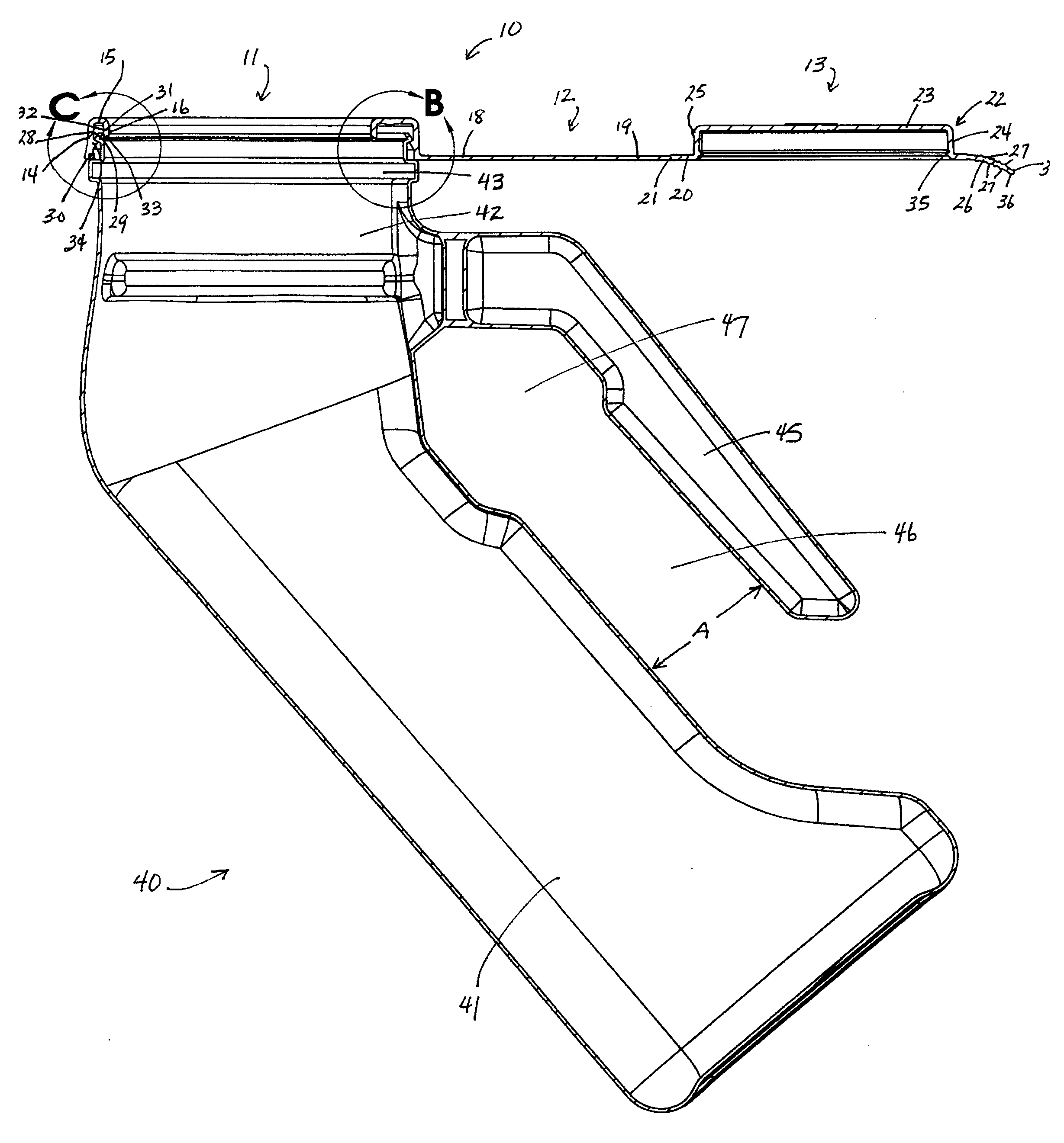
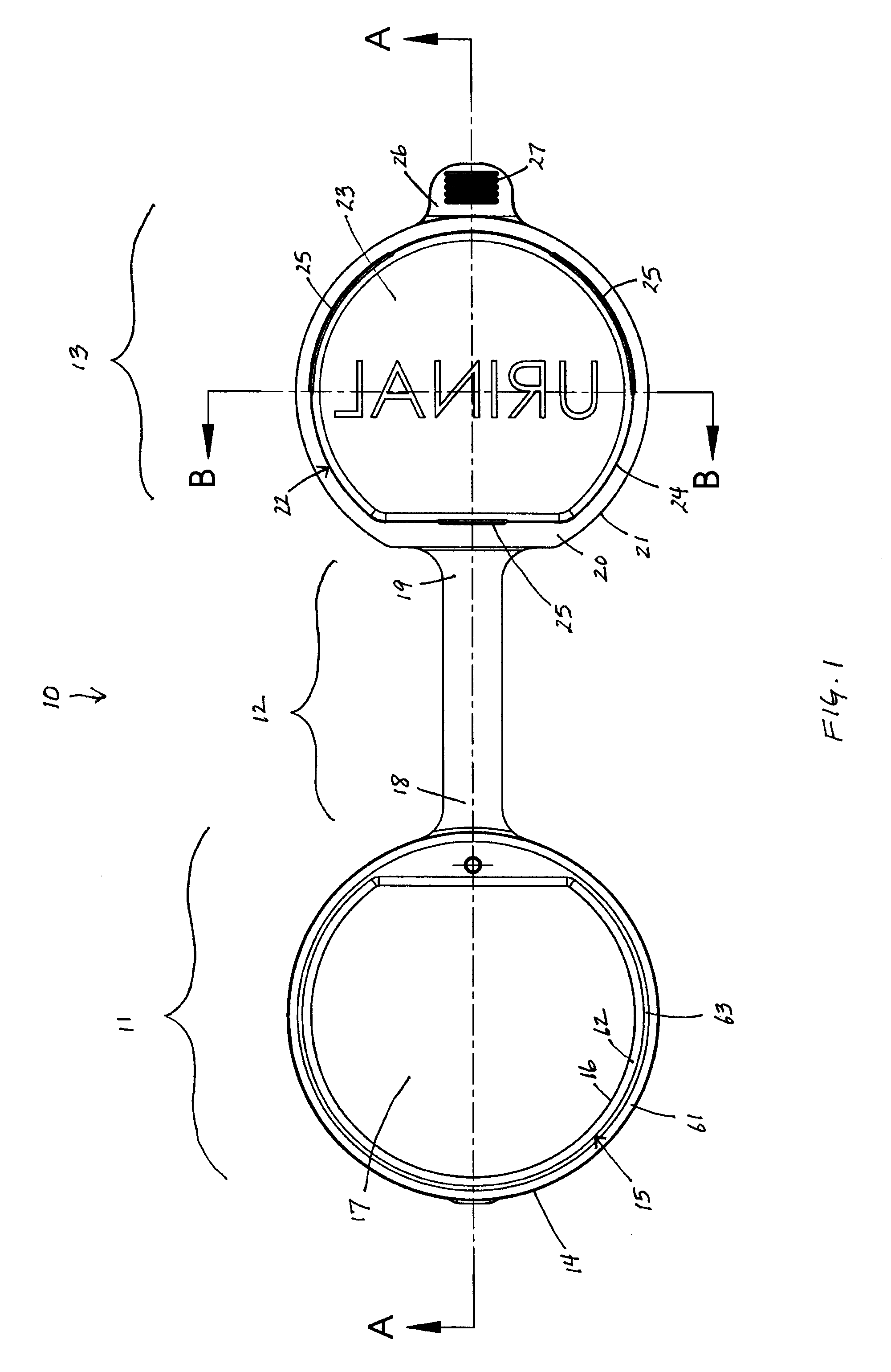
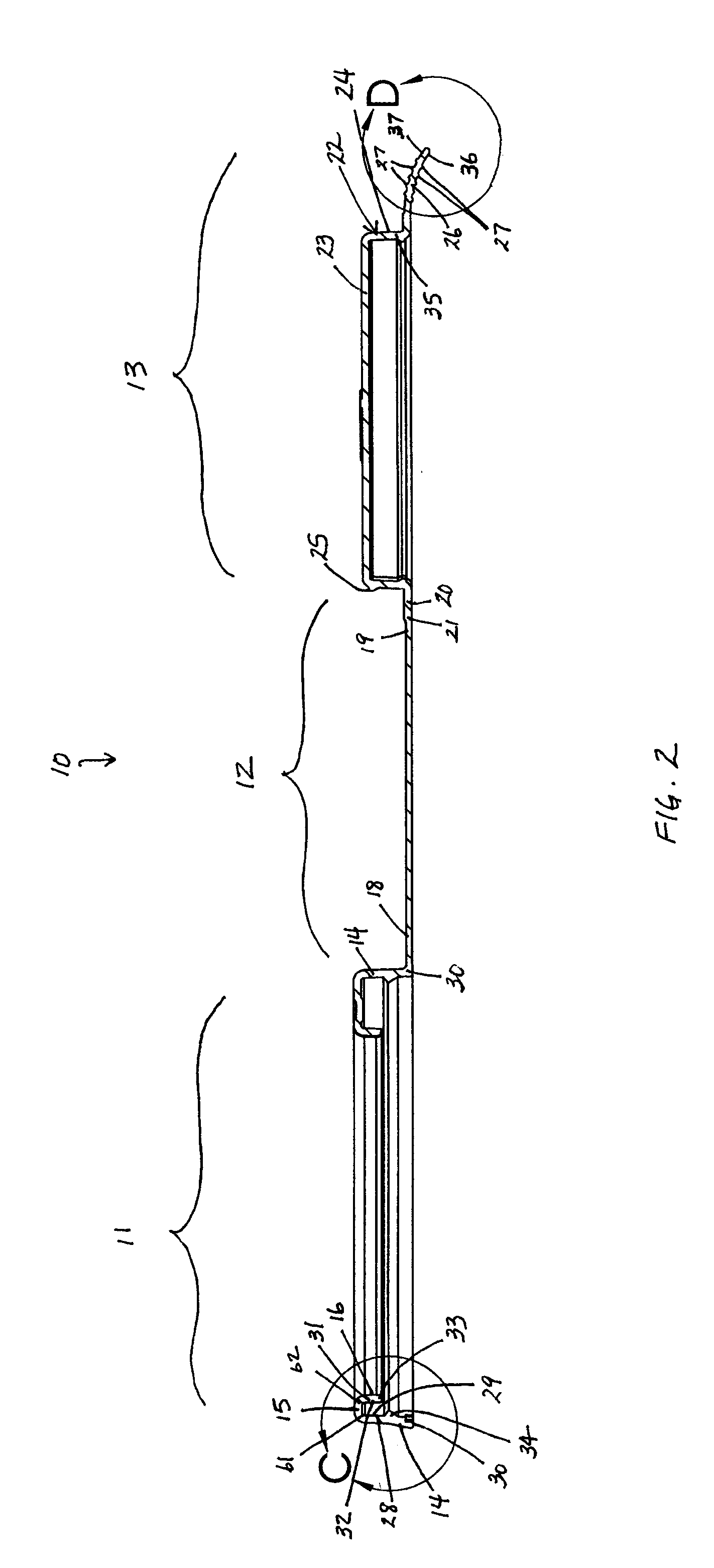
[0040]The present disclosure provides closures that cover or surround the sharp or rough edges of blow-molded containers, thereby overcoming some or all of the shortcomings present in current blow-molded containers, including, but not limited to, the risk of injury (laceration, abrasion, etc.) associated with the potentially sharp or rough edges. While the specific examples given here, for convenience of description and not limitation, is a blow-molded plastic urinal, it should be understood that the same principles apply to almost any blow-molded container having a less than smooth opening surface to be covered by the ring portion of the disclosed closure. Accordingly, the invention is applicable to and the claims are to be construed to cover all equivalent structures.

[0041]Turning to the figures, FIG. 1 shows a top view of one embodiment of the closure 10. The closure generally comprises three sections, the ring portion (or “ring”) 11, the hinge portion (or “hinge”) 12, and the li...


PUM


Abstract

A closure for a blow-molded container is disclosed, comprising a ring portion, a hinge portion, and a lid portion. Also disclosed are combinations of a closure and a blow-molded container, which in certain embodiments is a blow-molded urinal.

Description

CROSS-REFERENCE TO RELATED APPLICATION[0001]Not ApplicableSTATEMENT REGARDING FEDERALLY SPONSORED RESEARCH OR DEVELOPMENT[0002]Not ApplicableTHE NAMES OF THE PARTIES TO A JOINT RESEARCH AGREEMENT[0003]Not ApplicableINCORPORATION-BY-REFERENCE OF MATERIAL SUBMITTED ON A COMPACT DISC[0004]Not ApplicableBACKGROUND OF THE INVENTION[0005]1. Field of the Invention[0006]2. Description of the Related Art[0007]One method of manufacturing one piece, all plastic containers is by using an extrusion blow molding process. In this process, a molten tube of plastic is dropped between two halves of a mold. The mold halves are closed onto the molten tube. Then, compressed air is injected into the molten tube forcing the walls of the tube to expand into the mold, thus taking the shape of the cavity in the mold. The mold and molten plastic are cooled so that the plastic retains the permanent shape of the mold.[0008]When the mold halves are open, the plastic container is removed from the mold. A flashing...

Claims


Application Information

Patent Timeline
IPC IPC(8): A61F5/44B65D43/16
CPCA61G9/006B65D41/185B65D2543/00509B65D47/141B65D2543/00435B65D47/0842
Inventor ADAMS, CHUCK
Owner MEDICAL ACTION INDS
Learn More